Is A
Robot Getting Your Job?

According
to Light
Reading, n the last few weeks, five of the world's
biggest service providers have collectively announced plans to
cut 36,500 jobs, a figure that equals about 8% of their total
headcount at the last reckoning (see table below).
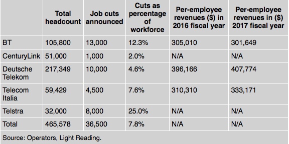
The layoffs
are a sign of the upheaval that is sweeping through the sector
as a result of automation, merger activity and the relentless
drive for efficiency. They will come after the world's 20
largest operators with headquarters in western Europe or North
America slashed more than 107,000 jobs during the past two
fiscal years. Four of the five players that have recently
announced redundancy plans are among the 20.
Despite this reality, some companies and spokespeople insist the
purpose of automation is not to reduce headcount, but rather to
improve customer services and working conditions. Thanks to
automation, they say, employees will spend less time on boring
and repetitive tasks. Another argument is that automation will
give rise to new, unforeseen jobs. The uncertainty is whether
these jobs will be in the telecom sector. It is entirely
conceivable that automation decimates this industry while others
flourish. After all, such "creative destruction" has occurred in
previous waves. The percentage of US workers employed on farms,
for instance, has dropped from about 50% in 1900 to just 2%
today.
FirstNet
Shows What Next Generation Wireless Can Do
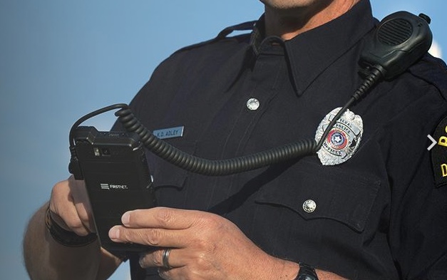 FirstNet photo
FirstNet
is a wireless broadband network on the AT&T cellular
network for first responders - police, fire, parametics, and
others involved in public safety. In the past, these services
have used many different types of radios for communications,
some of which are quite dated and many are unable to connect
with other types of radios. FirstNet is designed to solve
these problems by providing a network using regular cellular
service, with a big advantage - prioritization.
FirstNet
is just traffic on the regular AT&T cellular system but
FirstNet users have priority; they can bump others off the
network when they use the system for emergencies. This is done
by "slicing" the network dynamically. Slicing is a technique
being designed into 5G cellular systems, but as FirstNet shows
can be used with 4G/LTE networks also.
The
concept of slicing is useful for others that need priority or
low latency wireless communications. Utilities use wireless
but are concerned that high usage times cause high latency or
blocking. When vehicle-to-vehicle and
vehicle-to-infrastructure communications to support autonomous
vehicles, it too will need low latency, priority
communications to ensure safety. Obviously someone watching
video entertainment or playing online games would get lower
priority than devices where public safety is involved.
FirstNet
allows the use of standard cellular devices like smartphones
and tablets to be used by public safety personnel. The
FirstNet network is just getting introduced in some areas, but
developers are already developing apps for these devices to
take advantage of FirstNet.
The
physical network for cellular does not change for the slicing
concept; it's all done in software. But it requires the same
expansion in bandwidth and coverage that we've been discussing
here in the FOA Newsletter - a major expansion of fiber optic
backbones to support the network, especially all the small
cells necessary in urban areas.
Read
more about FirstNet
here
and here.
Have
Smartphone Sales Peaked?
The telecom
industry focuses on where the growth is. They thought long
distance and the Internet was the place to focus in the late
1990s but that all ended when the "Dot Com bubble" burst. FTTH
kept their attention for a few years, until they were distracted
by the cellular market. Now they are focused on 5G, small cells
and delivering video to your smartphone. But they may not be
happy when they see this graph:
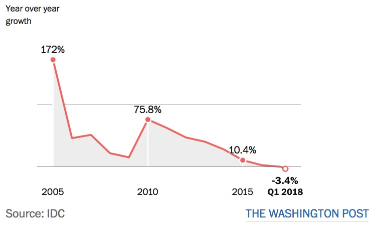
Smart
phones sales zoomed higher when the iPhone was introduced in
2007 and sales grew a whopping 75.8 percent - almost doubled
-between 2009 and 2010. But growth has been declining since -
note this is growth, not sales. Sales continued to grow until
this year, but a slowing rates. This year, however, we see sales
of smartphones actually declining.
This could be a problem. The cellular industry is making big
plans, al about 5G and small cells, but that also means big
investments - hundreds of billions of dollars in infrastructure
plus some big R&D bills. If the market is declining, they
can try to introduce new tech and features, the subject of the Washington
Post article we got this graph from to stimulate the
market, or maybe those plans will be revised.
Want To
Learn How To Pull And Blow Fiber?
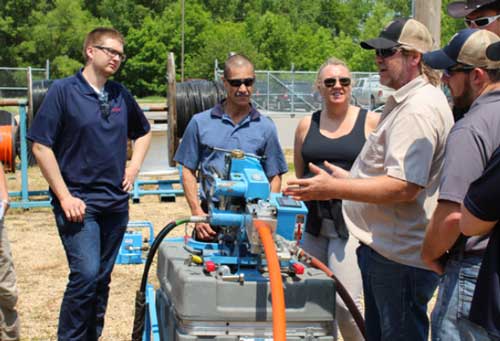 Condux photo
Condux International offers several product training sessions
each spring and fall. These classes are open to Condux
Distributors, Manufacturer Representatives and Contractors / End
Users. Each training day will focus on a specific market
segment. The Day 1 introductory session will provide a
foundation for those new to the industry - essentially an
industry overview. Days 2 and 3 will focus on the telecom and
power segments, providing an in depth look at each of their
product lines for that particular market.
Classes this Fall are being held September 11-13 and 25-27 at
Condux in Mankato, MN.
Go
here for more information.
What's
The Lifetime Of Fiber?
This month
we got an interesting question from a Project Manager at an
electrical utility: "The utility I work for has some FO cable
installed, some 20 years+ and I am wondering what is industry
standard for the useful life of a cable? This is from an asset
management point of view. I realize that FO cables can and do
last for decades, especially if the work on them is minimized
(ie. splicing for repair or relocation), but what would you
consider a good book value for useful life?"
Our Answer: Cable manufacturers have generally made fiber optic
cable for a lifetime of 20+ years and in the last decade or so
we’ve been told that 40 years is reasonable for a cable. But
that means the cable will retain its specifications for that
time frame. Networks, however, do not stand still. In the last
20 years, network speeds have increased by up to 100 times. In
the same time period, the fiber has been engineered to
accommodate longer and faster links. 20+ year old fiber was
installed when speeds were around 1Gb/s, where dispersion was
not an issue, nor was dense wavelength division multiplexing
(DWDM) being widely deployed.
So if you are using fiber at lower speeds, the current cables
are probably fine. You might have trouble splicing older fibers
in closures because the exposed fibers do tend to get brittle.
If you want to upgrade to faster speeds or DWDM, the older
fibers will need testing - we call if fiber characterization -
and here is a page in our FOA
Guide about it: Fiber
Characterization and Testing long haul networks (CD, PMD,
Spectral Attenuation)
Month's
"Best" Email Newsletter Subject: "Does DCO put ACO at
EOL?"
Lightwave
- Steven Hardy's Friday 5.
(We know Stephen well, so we expect he intended it to be
humorous.)
Looking
To Lease Dark Fiber? Fiber Connected Building? Here Is A
Source

We often get calls from users looking for a source of dark fiber
to lease. Keeping track of all the owners of optical fiber
networks and who leases dark fiber is a gigantic task, but FiberLocator
does exactly that.
FiberLocator is a telecommunications and colocation database
with detailed maps and information on hundreds of
facilities-based carriers, thousands of data centers and
hundreds of thousands of on-net buildings. Whether you need a
map for a project today or access to the FiberLocator database
for ongoing network planning and procurement needs, FiberLocator
has a solution for your business.
Another
Vendor Offers SOCs (Splice-On Connectors)
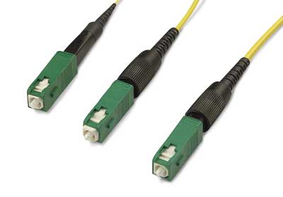
OFS Fitel has introduced their SOCs called the EZ!Fuse.
This
new “splice-on” connector (SOC) eliminates the need for
field polishing and significantly improves the quality of
the termination and installation time required. The
connector is easily assembled by using a process that
requires minimal skill or training. These connectors are
optimal for use in FTTx application. Both UPC and APC
polishing are available for single-mode fiber.
The EZ!Fuse
Splice On Connector is compatible with the Fitel Fusion
Splicers models Ninja, S179 and S178.
Read
the datasheet here.
Welcome
To New FOA Schools
This
month we've added two new schools in Canada.
Binesi
Training & Operations Centre - FOA
Approved School 371
Winnipeg,
Canada
TelecomTRAIN
- FOA
Approved School 370
Ontario,
Canada
What an
"intelligent traffic control center" looks like.
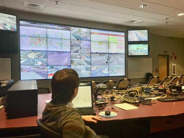
The wall of 24 video screens allows techs to view
intersections around the city of Mesa. New high-resolution
cameras provide amazing detail of the areas covered by video.
Traffic signals are programmed to adopt to traffic patterns,
such as when a local college has classes ending in the
mid-afternoon.
How To
Backfill A Trench
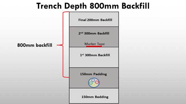
Here's the
answer to a question we've gotten. Where did we find the answer?
In Joe Botha's OSP Construction Guide which is published by the
FOA. Joe's book covers underground and aerial installation from
a construction point of view, covering material after the FOA's
design material and before you get into the FOA's information on
splicing, termination and testing.
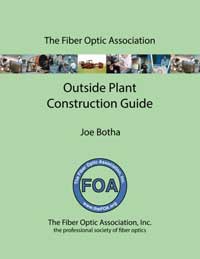
This is a
book that every contractor and installer should have for
reference. And since it was originally written for a course in
South Africa, its international in scope. You can get your copy
of the book from Amazon
or your local bookseller.
Reading
Between The Lines
We found an interesting article
in the Broadband Tech Report about AT&T. Here are a
couple of sentences that piqued our interest.
"AT&T has launched its gigabit-capable symmetrical
fiber-to-the-home (FTTH) Internet service in parts of South
Bend, IN. The service is now available in parts of 71 metro
areas. The deployment includes AT&T Fiber residential
Internet service, AT&T Business Fiber and a fixed 5G trial
using millimeter wave (mmWave) spectrum."
"The company says AT&T Fiber is now available to more than 9
million locations nationwide, with plans to reach at least 14
million locations across at least 84 metro areas by mid-2019."
We've written many times in this newsletter that the future of
cellular - small cells and 5G - depends on building a massive
fiber backbone. This seems to indicate that FTTH and cellular
can share the same infrastructure. That bodes well for both more
FTTH and cell services.
The
technical articles first printed in the April FOA
Newsletter have been incorporated into the FOA
Guide.
Power
budgets and loss budgets.
Power
meters measuring power.
1,
2 or 3 cable loss references.
Mode
power distribution.
Graded index
multimode fiber.
FOA Is
Testing A New Training Tool - A Video Microscope
FOA has
several vendors that are "training partners" who provide tools
and equipment to FOA approved schools at a discount for use in
their courses. One of those vendors is EasySplicer,
the maker of a low cost fusion splicer.. Another is Ripley,
the manufacturer of Miller strippers. Ripley recently acquired ODM,
a manufacturer of fiber optic test equipment in New Hampshire.
One of the ODM tools we have been interested in for use in our
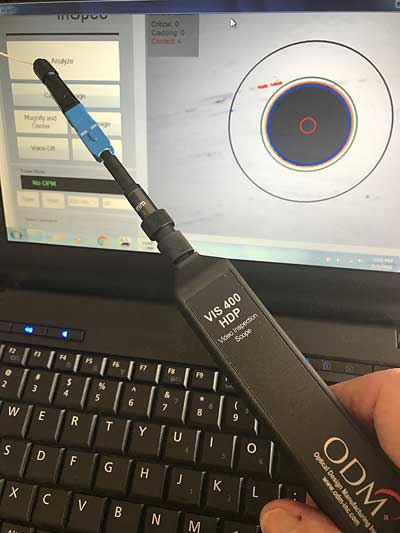
schools is the ODM
VIS 400 video microscope. A video microscope is perfect
for classes as it can be connected to a projector so all
students in a connector termination lab can see the endface of a
connector at the same time and discuss the condition.
Besides being used for examining connector polish during
termination, it is a way to illustrate graphically the process
of inspecting/cleaning/inspecting connectors, which involves
another FOA training partner, Microcare/Sticklers. When used in
conjunction with ODM’s proprietary InSpec™ software the VIS 400
ensures compliance with the IEC 61300-3-35 standard.
We're evaluating the ODM VIS 400 video microscope right now and
will be using it in selected FOA schools classes soon. We'll
report back on how it works in Future FOA Newsletters.
Conference
on Plastic Optical Fibers

The 27th International Conference on Plastic Optical Fibers (POF
2018) will be held in Seattle, Washington, USA, from September 4
to 6th.
The main theme for POF2018 is optical data networks and sensing
architectures, technologies, components, materials, tools and
techniques that utilize the advantages of POF.These technologies
are designed to meet the harsh environment of aircraft and
spacecraft applications on both commercial and military
platforms. This application-oriented conference will provide an
international forum for leaders, researchers, scientists, and
engineers from academia and industry to share new R&D
advances and discuss issues and solutions.
POF 2018 will also cover recent developments in POF technology,
applications, technical standards, industry progress and new
markets. Speakers from around the world will review
opportunities for POF in areas such as automobile applications,
Gigabit POF, 4K/8K ultra high definition television (UHDTV),
home networking, active optical cables, POF sources &
sensors, and high-temperature POF, among others.
For more information on POF 2018, including registration,
exhibiting or submitting a paper, go to the POF
2018 website.
How
"Fast" Is Fiber?
One
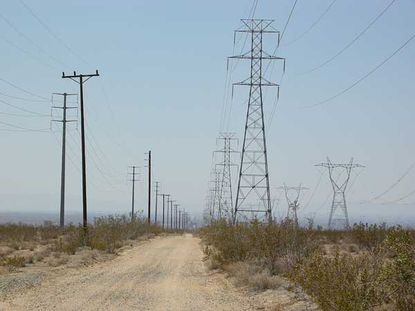
of the FOA instructors sent us this question: "I work
with at Washington Univ with an engineer who works for an
electrical utility. He asked a question about the speed of
signal transmission over fiber optics, single mode, at top of
towers. They need signal to be sent in 18 millisecs for relays
to function properly. Is there a problem over a distance of
150 miles?"
Let’s do a calculation:
C = speed of light in a vacuum = 300,000 km/s = 186,000
miles/sec
V= speed of light in a fiber = c/index of refraction of fiber
(~1.46) = 205,000 km/s or 127,000 miles/sec
150 miles / 127,000 miles/sec = 0.00118 seconds or ~1.2
milliseconds
Another way to look at it is 127,000 miles/sec X 0.018 seconds
(18ms) = 2,286 miles
So the fiber transit time is not an issue. The electronics
conversion times might be larger than that.
I used to explain to classes that light travels about this fast:
300,000 km / sec
300 km / millisecond
0.3km /microsecond or 300m / microsecond
0.3 m per nanosecond - so in a billionth of a second, light
travels about 30cm or 12 inches
Since it travels slower by the ration of the index of
refraction, 1.46, that becomes about 20cm or 8 inches per
nanosecond.
That is useful to know since an OTDR pulse 10ns wide translates
to about 200cm or 2 m pr 80 inches (6 feet and 8 inches), giving
you an idea of the pulse width in distance in the fiber or an
idea of the best resolution of the OTDR with that pulse
width.
Why You
Clean Connectors Before You Make Connections
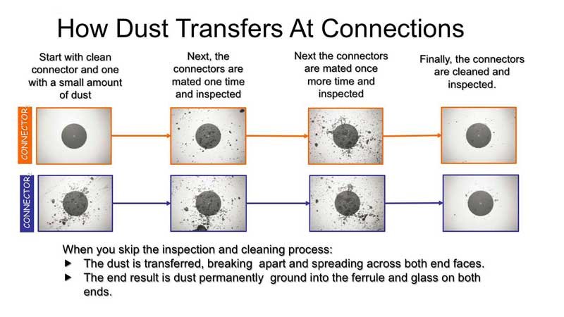
Brian
Teague of Microcare/Sticklers
send us this series of photos showing what happens when you make
connections with dirty connectors. It speak for itself!
Recycling
Fiber Optic Cable
We
received this note from Steve Maginnis, LD4Recycle/ CommuniCom
Recycling on recycling fiber optic cable:
We have 3 Processors gearing up to accept fiber optic
cable (FOC). As we all know, all FOC is not the same. Several
truckloads of “typical” FOC scrap from FOC mfgrs and “typical”
FOC and Coax cable have been studied and tested.
Therefore, today you can begin contacting me with the type FOC
material or scrap you toss to the landfills today. We need to
quantify the expected feedstock. Our expectation for quantities
is quite large (tons) but there is a capacity limit. And I do
have several processors that can take ALL materials and others
that can accept LIMITED types of FOC material and quantity.
Contact:
Steve Maginnis
LD4Recycle/ CommuniCom Recycling
(Visit our new
website)
sm@LD4Recycle.com
803.371.5436
Color
Codes Added For 16-Fiber MPO Connectors
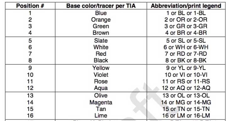
There is a
new standard for MPO connectors with 16 fiber rows. Now we need
color codes for fibers 13-16 and they have been selected, as
shown in this table.
If you are familiar with the MPO standards, there are dozens of
pages of diagrams for polarity on the 12 fiber MPO. Wonder how
many there will be for this one?
Best
Practices Guide For Underground Construction

We assume
you are familiar with the "One Call" and "Call Before You Dig"
(811) program, but are you also familiar with the people behind
it - the Common Ground Alliance and their Best Practices
website?
CGA
is a member-driven association of 1,700 individuals,
organizations and sponsors in every facet of the underground
utility industry. Established in 2000, CGA is committed to
saving lives and preventing damage to underground
infrastructure by promoting effective damage prevention
practices. CGA has established itself as the leading
organization in an effort to reduce damages to underground
facilities in North America through shared responsibility
among all stakeholders.
Officially
formed in 2000, the CGA represents a continuation of the
damage prevention efforts embodied by the Common
Ground Study.
Sponsored by the U.S. Department of Transportation and
completed in 1999, this Study represents the collaborative
work of 160 industry professionals who identified best
practices relating to damage prevention. Any
best practice or program endorsed by the CGA comes with
consensus support from experts representing the following
stakeholder groups: Excavators, Locators, Road Builders,
Electric, Telecommunications, Oil, Gas Distribution, Gas
Transmission, Railroad, One Call, Public Works, Equipment
Manufacturing, State Regulators, Insurance, Emergency
Services and Engineering/Design.
Read
the CGA Best Practices Guide here.
Here
are all the CGA resources for damage prevention.
Welcome
New FOA Corporate Members
The
following companies are new corporate members this month. You
can find more information on these and hundreds of other FOA
Corporate Members in our FOA Corporate database
in map
and list
form.There you will find many companies involved in fiber
optics that can help you with products and services to fill
your needs.
Consult-comm,
Sanford FL
Combotech,
Athens, Greece
Poirier
Telecom, Ballinafad Ontario, CA
Profy
Technologies, Sandton South Africa
Keeping
Up To Date With Fiber Optics And Premises Cabling
We just
finished updating two of the books and a third is in the works.
Along with the changes we make to the books, we update the FOA
Guide with the same materials. Here is a rundown of the updates
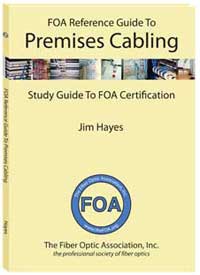
we have just completed of The
FOA Reference Guide To Fiber Optics and The
FOA Reference Guide To Premises Cabling. We
should have the last updates - The FOA Reference Guide To
Outside Plant Fiber Optics - completed by next month.
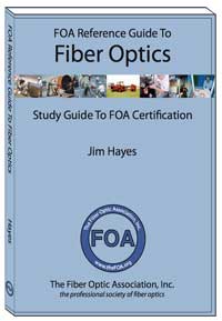
The FOA Reference Guide To Fiber Optics has been updated
to cover some new technology like bend-insensitive fiber, OM5
fiber, SOCs (fusion splice-on connectors), microcables and
microducts. We added information on datalinks on a single fiber
like PONs, DWDM and CWDM. We expanded the chapter on testing to
include much more information on visual
inspection and connector cleaning,
OTDRs and Fiber Characterization. The same updates have been
made to the online material in Fiber
Optics - The Basics in the FOA
Guide online
Premises cabling has not been standing still either. We did many
updates to the The
FOA Reference Guide To Premises Cabling this time. We
updated the cable types to include Cat 8, added a section on
PoE (power over Ethernet), explained the nomenclature used
in the latest TIA 568 standards, added information on POLs
(passive optical LANs), DAS (distributed antenna systems for
cellular) and a complete new Appendix on Data Centers. In
the fiber optic chapter, we expanded the material on fiber
to include POLs, visual inspection and connector cleaning
and OTDR testing. The
same updates have been made to the online material in Premises
Cabling in the FOA
Guide online. We also
added a new page just on
PoE (Power over Ethernet) to explain its background,
applications and potential issues.
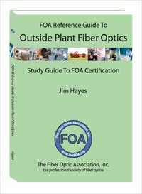
We have also updated the FOA Reference Guide To Outside
Plant FIber Optics. It has
been updated to cover some new technology like
bend-insensitive fiber, OM5 fiber, SOCs (fusion splice-on
connectors), microcables and microducts. We added information
on datalinks on a single fiber like PONs, DWDM and CWDM. We
expanded the chapter on testing to include much more
information on visual
inspection and connector cleaning,
OTDRs and Fiber Characterization.
So if you look up information on the FOA
Guide online
or purchase a FOA printed textbook you will now have the latest
information. Since we've been updating our reference materials
used for training, the related courses on Fiber
U are updated also. Finally, we're updating our curriculum
used by FOA approved schools to ensure their students get the
latest information.
This is just another way that FOA tries to make the most
up-to-date, technically correct information available to
everyone in the industry.
A Short
(Pictorial) History Of Modern Telecommunications
FOA has
been asked a lot of questions about how modern
telecommunications developed. We've been adding information
about the history to some of our seminars and recently to our
curriculum presentations. The
FOA history follows the development of modern communications
through Bell, Marconi, De Forest, Shannon, Kao and the
personnel at Corning and Bell Labs who have made modern
communications possible.
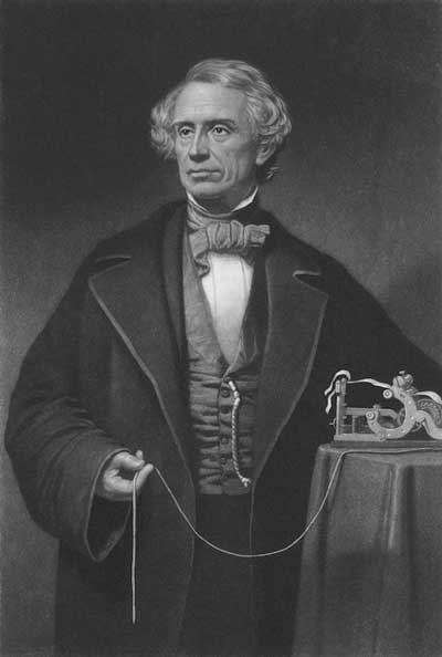 Morse and his telegraph
We think you will find A
Short History of Modern Telecommunications
interesting. Next we'll add articles on LANs and structured
cabling and the development of fiber optics.
Trivia for photographers: this photo of Morse was taken
not long after photography began in America - the early
1840s. The original is now on display in the Getty Center
in LA as part of an exhibition of early American
photography.
A
Conversation About Fiber And Testing
Recently an
extended conversation between Eric Pearson and Jim Hayes, both
FOA founders, covered the issues of testing fibers at multiple
wavelengths. We've summarized the conversation here because
there is some very interesting and useful information in it.
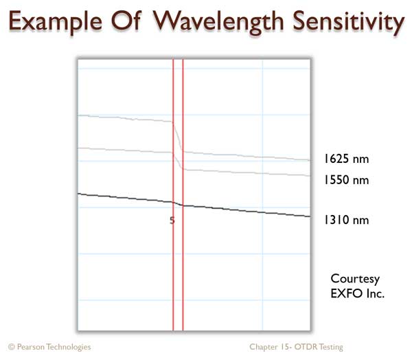
March 2018 update: Here is a OTDR trace from EXFO Eric
uses in one of his books to illustrate bend sensitivity of fiber
and different wavelengths:
And our conversation from February 2018:
EP: Testing multimode fiber at both wavelengths (850 and 1300nm)
has been recommended to evaluate the presence of stress. If EF
(encircled flux) testing fills the 30µ center of the core and
1300 nm testing fills the entire core, is it possible that this
difference in core fill would indicate stress, even though there
is no stress?
JH: There are definitions for EF testing at 1300nm for multimode
with similar mode fill requirements included in various
standards documents that cover EF so there should be no
difference in stress loss due to mode fill. However, you need a
1300nm EF source. But using 1300 nm for finding stress
loss may be irrelevant since the majority of multimode fiber
today is bend-insensitive (BI) fiber. That's becoming true for
more singlemode fiber also, as BI SM fiber is used in
microcables, spider ribbons and other new cable types.
EP: Is there any reason to test multimode at both 850 and 1300
nm then? How about SM at both 1310 and 1550?
JH: The issue of dropping 1300nm testing of MM fiber has been
discussed in standards committees for years. Since the advent of
the cheap VCSEL - which of course is only feasible at 850nm -
there is practically no use of MM fiber at 1300nm and no real
reason to test at that wavelength. But just try to remove
something from a standard - it's just about impossible!
The issue of SM fiber at 1310 and 1550nm is different. Today
most SM fiber is probably used at both 1310 and around 1550nm
with DWDM systems and PONs, so testing at both wavelengths is
necessary. Much of the testing of SM fiber for stress is done by
OTDRs at 1625nm anyway, but I do not know how that is affected
by BI fiber structures.
The whole topic of testing MM fiber skirts the BI fiber issues.
Controlling mode distribution in BI fiber is problematic. Those
20-25mm mandrels you used for regular MMF don't work with BI
fiber. It takes a mandrel ~6mm to produce the same mode
filtering as a 20-25mm mandrel, but then the BI fiber structure
simply refills the higher order modes. Creating EF in BI fiber
is questionable. Standards have recommended against using BI
fibers for reference cables (because it produces higher losses
than mode-filtered regular fiber) but you are probably testing
cable plants with BI fibers. Finding non-BI fiber patchcords to
use for reference cables is difficult since most MM fiber is BI.
Some manufacturers have made nothing but BI fiber for nearly a
decade!
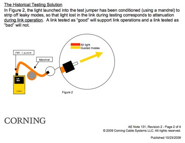
Historical Footnote 1: As an example of how long this
issue has been discussed, look at these two clips from Corning
AEN-131 from 2009.
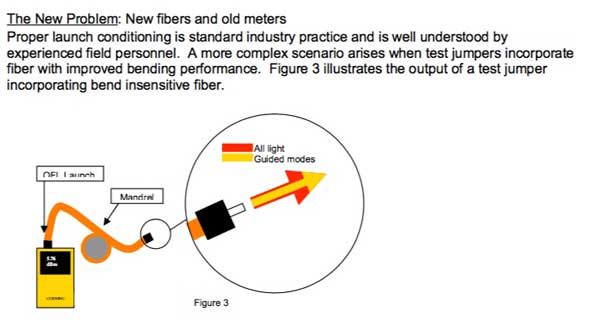
Historical
Footnote 2: While searching for this ap note (we
found it in our own files where we had downloaded it in 2010),
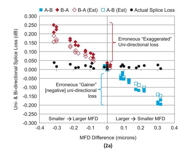
we found another interesting Corning ap note, AN3060,
March 2014, on OTDR testing of SM fiber fusion splices.
What interested us was this graph, showing OTDR loss measurement
differences depending on direction and mode field diameter
differences.
We remembered another graph similar to this that we (JH) created
30 years ago. You can tell its age by the crudeness of the
computer generated graph from Lotus 123, an early spreadsheet
program.
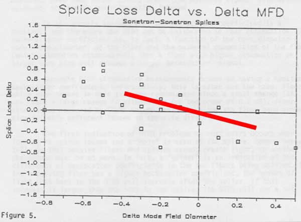
This data was taken with some early singlemode fibers and an
early OTDR from a sample of Spectran SM fiber spliced to Corning
fibers. The work was done for Spectran to show their fibers
could be spliced to Corning fibers. We obtained the data from a
contact at Spectran specifically to analyze for directional loss
differences and show why "gainers" happened. This graph was one
of two graphs that showed the reason - gainers were caused by
backscatter differences in fiber of differing mode field
diameters (MFD.)
Out of curiosity we overlaid a red line showing the modern
Corning data and the similarity is obvious. The scattering is
much less because fibers today are much more consistent
(Corning's largest MFD difference was 0.3 microns and the 1980s
fiber MFD varied up to 0.8 microns, a combination of actual
fiber variations and the greater errors in measurements then)
and modern OTDR data is undoubtedly more consistent too.
In our analysis of the data, we also had data on the attenuation
coefficient of the fiber, so we looked at another relationship
that we thought would be useful - loss difference vs the
difference in fiber attenuation coefficient.
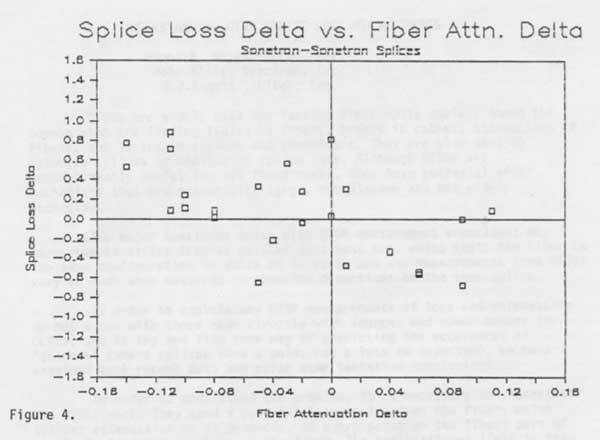
Within the limitations of the data, it's obvious that the
directional difference in splice loss is also related to the
difference in the attenuation coefficient of the fiber. We found
this very interesting because most techs running OTDR tests do
not have data on MFD but they can easily measure the attenuation
coefficient of the two fibers being spliced. With these early
fibers, a difference in fiber attenuation of 0.1dB/km would
indicate a loss difference of around 0.4dB. Looking at the
difference in fiber attenuation could provide an indication of
the potential error of the OTDR loss measurement.
OTDRs could easily calculate this - the data is imbedded in the
LSA splice loss measurement. Perhaps if someone would repeat the
Corning test with modern fibers and duplicate the graph above to
show the relationship of difference
in the attenuation coefficient to the difference in splice
loss and it looked better - like the Corning data on modern
fibers - the OTDR manufacturers might incorporate this and
provide a better single-ended splice loss test.
Nitpicking: The Corning graph has a series of black
dots labeled "Actual Splice Loss." In the paper they refer to
them as " bi-directional
averaged (actual) splice loss values." While that is a
commonly accepted fact, technically it's inaccurate. It is
really an average splice loss for the two directions, because
if you measure the actual loss of a splice between two fibers
in each direction, you will find the difference in MFD will
cause real differences in loss in each direction. Measuring it
is non-trivial, however, and the difference is small with
small MFD differences. We go into this in the new FOA book on
testing.
 FOA
Reference Guide To Fiber Optic Testing FOA
Reference Guide To Fiber Optic Testing
OTDR
Testing FTTH PONs
We've spent
some time on this topic ourselves, noting that downstream
testing is confusing and upstream testing is the only solution.
But FOA Master Instructor Joe Botha of Triple
Play Fibre Optics in South Africa has encountered a
new issue - drop cables are often BI fibre (G.657A) while feeder
and distribution cables are regular G.652D. He's done some
research on the issues and written an article for a website in
South Africa we can share with you.
Read
more.
PoE And
Counterfeit Cable
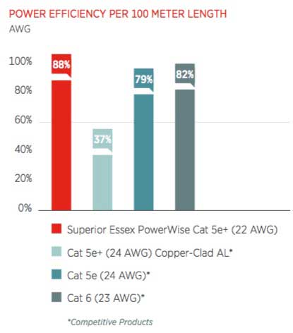 Superior Essex Comparison Of Cable Efficiency
This
graph showed up in an interesting
white paper on PoE from Superior Essex, LeGrand and Fluke.
You might remember we did an analysis of PoE power efficiency
in the November
FOA Newsletter article "PoE Analysis From The Ethernet
Alliance (With Our Analysis). This graph has some data
we did not consider - the efficiency of counterfeit cable that
uses copper-clad aluminum conductors instead of pure copper.
The inefficiency of this cable means that more than half the
power will be lost in transmission - not only inefficient but
dangerous as the power lost is converted to heat. Considering
that the samples of counterfeit cable that we have tested use
flammable insulation and jackets, that could be a very
hazardous application!
Recent conversations with people involved with adding PoE
applications to the US National Electric Code bring up a
further problem. The IEEE did not register "PoE" as a
trademark so it's being used to describe applications like
daisy-chained lighting and cables longer than the 100m limit
of Ethernet. This makes the safety considerations even more
important - and scary.
FOA is researching PoE as part of our CPCT
certification and have created a FOA
Guide page on PoE which we will be updating regularly.
 Comments
I
just completed the CFOT Certification course at EIA in
Akron, PA with Arnie Harris and I have to say that his
training and your books are some of the best I have
seen. The Book was easy to read and to understand, Arnie
explained everything at a level we could understand and
then expanded on the information as we learned more and
more. It was some long days and it was worth it! Thank
you and Thank you, Arnie Harris, for the great teaching!
It is much appreciated! I will be back again to take
more of your courses!
EIA
- FOA School #195.
FOA
Facts
FOA is a
non-profit professional society whose members are all certified
techs - mostly CFOT®s
-Certified Fiber Optic Technicians - but also may be CPCTs -
Certified Premises Cabling Technicians or corporate
members involved in fiber optics.
FOA is a "virtual organization" - we have no "brick and mortar"
presence. We operate over the Internet with operations centered
in California, with active workers and volunteers in locations
as diverse as Texas, Ohio, Canada, Singapore, Malaysia, Denmark,
South Africa, the Middle East and many more.
Being a virtual organization, FOA has very low overhead,
allowing us to offer cost-effective certifications and many free
programs to support our industry.
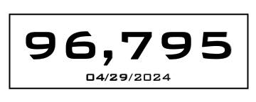
As of today, FOA has certified this many techs. About 90% come
from our schools but many experienced techs have become FOA
CFOT-certified directly through our "Work-to-Cert"
program.
FOA has almost 200 approved training organizations in about 40
countries around the world around the world.
FOA has 14
fiber optic certification programs covering every aspect
of fiber optic network design, installation and operation.
Primary
Certifications: CFOT (basic fiber), CPCT (premises cabling),
CFOS/O (outside plant, taught with CFOT included) and CFOS/D
(fiber optic network design).
Skills Certifications (for installers and techs, requires
CFOT): CFOS/S (splicing), CFOS/C (connectors/termination),
CFOS/T (testing), CFOS/FC (fiber characterization).
Applications Certifications (for techs or anyone, including
managers and supervisors): FTTH (fiber to the home), CFOS/L
(optical LANs), CFOS/DC (data centers), CFOS/A (fiber to the
antenna), CFOS/DAS (distributed antenna systems) and CFOS/W
(fiber for wireless)

FOA monitors the trade press, websites and other
resources continually to look at what's happening in many
technologies that affect fiber optics. We're tracing
technologies as diverse as wireless, IoT, autonomous vehicles,
smart cities, energy, or anywhere fiber is used to bring news to
our readers.
FOA continually updates our technical materials, online and
printed, and our curriculum to ensure our readers have access to
the latest technical information and our schools teach the
latest technology and applications. Our printed books are being
updated right now.
FOA created the
FOA Online Guide as a non-commercial trustworthy technical
reference almost a decade ago so the industry would have a
reliable technical reference. In the last year, over 1million
visitors downloaded about 4 million pages of technical
information.
FOA offers free online self-study programs at Fiber
U. In 2017, the number of online sessions doubled to
200,000. Many of those are preparing for FOA certification
programs - taking courses at our schools or using the "Work-to-Cert"
program. Some of our schools are requiring Fiber U programs as
prerequisites for their classroom courses so they can spend more
time on hands-on activities.

FOA offers over 100 educational YouTube
videos that have been viewed 2.4 million times.
FOA offers its training programs to other organizations at no
cost to help them train their members properly in fiber optics.
For example, FOA has been working with the Electrical Training
Alliance (IBEW/NECA) for over 20 years, training their
instructors for their apprenticeship programs. We work with many
other organizations and companies to provide the materials they
need.
FOA has about 300 corporate
members - companies in various aspects of the fiber optic
industry worldwide that we list online and offer discounts on
certifications and renewals.
FOA provides speakers for many conferences and even
presentations for use by other organizations to educate people
on the aspects of fiber optic communications.
FOA has a program to provide classroom
materials for STEM
teachers (science, technology, engineering and math)
introducing K-12 students to fiber optics and creating science
projects.
FOA provides forums for discussion on various social media. Our
LinkedIn groups have about 5,000 members each. If you are not
joining us on social media yet, please do.


New
From FOA
New FOA
YouTube Video
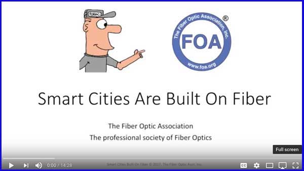
Everyone's talking about "Smart Cities" but what makes a city smart? It's a combination of services that will be delivered over an extensive fiber optic network. This video examines an advanced Smart City, Santa Monica, California, and looks the current services that make it a smart city today and what possible services can be delivered in a Smart City over fiber in the future.
Smart Cities Are Built On Fiber on YouTube
New FOA "Fiber For Wireless"
Curriculum And Certification

Fiber has become the critical part of the infrastructure for the
expansion of wireless communications. Just a few years ago,
fiber was used to connect cell sites to the telecom system and
backbones for enterprise LANs that were adding WiFi wireless
access points. Now mobile devices and demand for bandwidth are
driving major changes to these applications.
Today, we have LTE and 5G coming, RAN and Gigabit WiFi. We need
fiber backhaul to the traditional cell sites and up the tower to
the antennas, new architectures like fiber fronthaul or C-RAN
that support the traditional cell sites plus small cells and DAS
- distributed antenna systems inside buildings and campuses. We
have enterprise WiFi, metro WiFi and even rural WiFi being used
for broadband Internet. All depend on a fiber infrastructure to
deliver sufficient bandwidth to meet user demands.
FOA has created a “Fiber For Wireless” program to cover all
these applications (and define all the TLS - three letter
acronyms - so loved by tech industries!) We talked to managers
and technicians at telcos who are looking at all types of
wireless options, contractors who focus on wireless
infrastructure of all types, metro and utility personnel who use
all types of communications and of course manufacturers of these
new products.
Who’s
the audience? People who just want to know about the
intersection of these two modern, fast changing technologies.
The FOA “Fiber For Wireless” application specialist curriculum
and CFOS/W certification will give you the background you need
to understand the dynamics of today’s mobile applications and
prepare you to participate in those technologies. Look for it to
be available from select FOA schools and online at Fiber U in
the very near future.
Have
You Downloaded Your Copy Of The Updated ANSI/NECA/FOA Fiber
Optic Installation Standard Yet?
Available
Free Courtesy of FOA
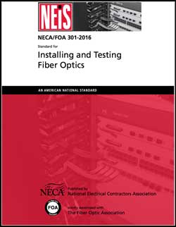
NECA/FOA-301was
created to be a document that could be used as a guide to
installation practices and also be quoted in project paperwork
to define what was meant by installation in a "neat and
workmanlike manner." This standard was the first standard to
approach the issues of installation of fiber optics in a
document that could be used by network owners, project
managers, contractors, installers, test techs, maintenance
personnel and even the manufacturers making the products being
installed following this standard.
Go
here for more information on NECA/FOA-301
and directions for a free download.
FOA's
Latest Textbook - Fiber Optic Testing

FOA
Reference Guide To Fiber Optic Testing
Libro
de Diseño para Redes de Fibra Óptica en
Español - FOA
Design Book Available In Spanish - Online
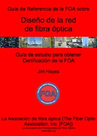
FOA has translated the FOA Guide To Fiber
Optic Network Design book and made it available online to
those studying for the CFOS/D Certification but whose native
language is Spanish. You
can access the Spanish translation of the Design book here.
A printed version will be available in the near future.
FOA
YouTube Videos Now "Closed Captioned"
FOA's
YouTube videos are very popular as you can see from the
statistics above. We have had requests from teachers and viewers
for closed-captioning. Now FOA is upgrading all its YouTube
Videos to offer "closed captioning" for those with hearing
disabilities - or if you want to view the video quietly and
don't have headphones. FOA used a highly-regarded service that
does closed-captioning for many of the television networks to
ensure accurate captioning.
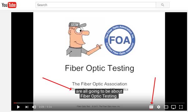
The closed captioning can be turned on by the small "CC" button
on the lower right side of the video (right arrow). The
captioning shows up on screen in white letters on a black
background (left arrow). You can view
this video on fiber optic testing here, and try the "CC"
button to see how it works.
We hope our viewers find this helpful.
FOA has over 100 YouTube videos on fiber optics, premises
cabling and the fiber optic job marketplace. Here
is a list with links to them online.
New
Website Keeps You Up To Date On Structured Cabling
Liz
Goldsmith, manager of the TIA Fiber Optic Technology Consortium
(FOTC) has started a new website that aims to keep readers up to
data on the news and products in the structured cabling
(premises cabling) space. Called Structured
Cabling News, it offers news about the industry in more
than a dozen categories so you can browse the news by categories
(like fiber) that interest you most. Liz sums up the aim of SCN
as "SCN brings you current Structured Cabling News curated by
category and topic. We search the 'Net so you don't have to -
updated daily with industry trends, new products and best
practice from industry leaders."
And you can subscribe to daily or weekly digests to keep
yourself informed.
Structured
Cabling News
Interested
In A Career In Fiber Optics?
FOA has created a new YouTube video to introduce students to
careers in fiber optics. It was made for showing to high school
and junior high students interested in tech careers but anyone
interested in a possible career in this field will find it
interesting. If you have kids in school or know teachers, let
them know about this too. Watch the FOA
Careers In Fiber Optics Video on YouTube and visit the FOA
Careers In Fiber Optics web page at www.foa.org/careers/.
New
Viavi Database Illustrates More Than 500 Operational or
Planned Deployments Of Gigabit Broadband Globally

Communications service providers worldwide are accelerating
efforts to deliver gigabit internet -- network speed that is 159
times faster than the global average of 6.3 Mbps. The Gigabit
Monitor, a visual database referencing current and planned
gigabit deployments around the world, from Viavi Solutions (the
test equipement company formerly known as JDSU). The Gigabit
Monitor paints a picture of mobile, cable and telecom service
providers all racing to deliver lightning-fast internet
connectivity to meet end users' demands. The database, developed
completely from public information, is available at: http://www.gigabitmonitor.com.
Below are some of the key insights from the Gigabit Monitor:
- State
of gigabit: There are now at least 350 live gigabit
deployments globally, with a further 164 announced or under
construction, across wireline and wireless technologies
including GPON, DOCSIS 3.1, G.fast, LTE-A, 5G and 802.11ac.
- Contrasts
by region: North America has the largest share of announced
gigabit deployments, with 61 percent. Europe is second with
24 percent. Asia, Australasia, Middle East, Africa and South
America share the remaining 15 percent of deployments.
- Deployments
accelerate: The pace of gigabit deployments has accelerated
sharply. Over 70 percent of the live gigabit deployments
tracked have been launched since the start of 2015.
- Fiber
dominates: 85 percent of currently known gigabit deployments
are based on optical fiber connectivity. 11 percent are
based on Hybrid-fiber coax (HFC), a broadband technology
that combines optical fiber and coaxial cable, commonly
employed by cable providers.
- Wireless
gigabit is already here: Nearly 3 percent of known gigabit
deployments are based on LTE-A, a modified version of LTE
which is gigabit-capable.
- 5G is
coming fast: 37 wireless carriers have announced plans for
5G networks. Five of them plan to have 5G networks built as
early as 2017.

The word on
the "Dig Once" program is getting out - FOA is getting calls
from cities asking us for information and advice. It helps that
the current Administration is trying to convince cities of the
advantages of installing ducts or conduits when they dig up a
street so they don't have to do it again. Here are some links
for more information.
The DoT page on the administration’s Executive Order: http://www.fhwa.dot.gov/policy/otps/exeorder.cfm
From the Council of State governments: http://www.csg.org/pubs/capitolideas/enews/cs41_1.aspx
From the city of San Francisco: http://sfgov.org/dt/dig-once
An article about Dakota County, MN: https://muninetworks.org/tags/tags/dig-once
And
the one to download and hand out:
A “How To” Guide from The Global Connect Initiative: https://share.america.gov/wp-content/uploads/2016/04/6.-GCI-Dig-Once.pdf
Useful
Online Resources
We often
have contacts give us online links for useful information which
we like to share with our readers. Here are two:
Want To
Learn More About DIY FTTH?
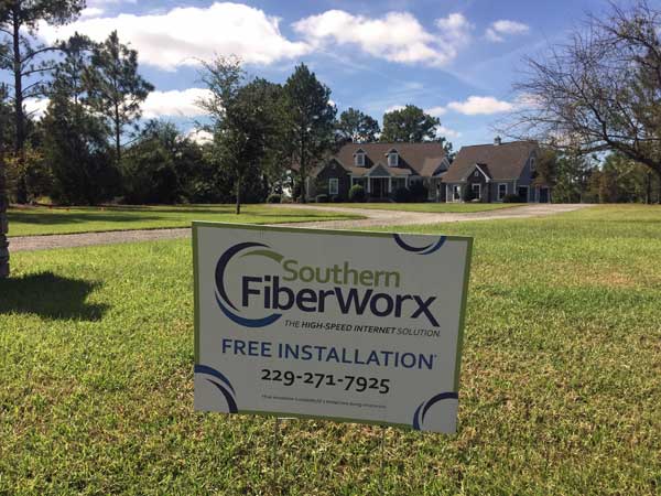 Southern
Fiberworx is a DIY FTTH Project in Georgia
It seems
like every week FOA gets another call from a town, real estate
developer or utility wanting to start a FTTH project for their
area. FOA has created several videos and a a web page on this
topic to help anyone get started.
FTTH
Case Studies: Do-It-Yourself FTTH
FOA has a
series of videos on do it yourself (DIY) FTTH. The first three
videos are online now:
FOA
Lecture 45 Do It Yourself FTTH (Fiber to the Home) What's
involved in building a FTTH network of your own.
FOA
Lecture 46 Do It Yourself FTTH (Southern Fiberworx)
(FOA Newsletter
November 2015) How one company, Southern Fiberworx in
Cordele, GA did it themselves.
FOA
Lecture 46 Do It Yourself FTTH (Southern Fiberworx)
(FOA Newsletter
November 2015)
Why
We Warn You To Be Careful About Fiber Shards
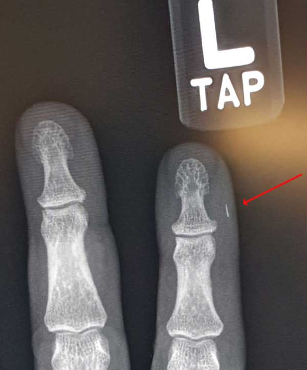
Photo courtesy Brian Brandstetter, Mississauga
Training Consultants
1-844-440-0047
www.fiberoptictraining.com
Another
Source Of Articles On Fiber
FOA
President and editor of this newsletter Jim Hayes has also been
writing a column in Electrical
Contractor Magazine for more than 15 years now. Electrical
contractors do lots of fiber work and this column has covered
some toics they are interested in including installation
processes, network design, fiber applications and in the last
year, a lengthy series on dark fiber - what it is, how's its
used and how it benefits the growth of communication. A recent
web site redesign makes it easier to browse all these articles -
just go to http://www.ecmag.com/contributing-authors/jim-hayes
and you can see all of them.
Fiber
Optic Education For Students At Any Age
We hear
about fiber optics all the time - it's in the news whenever we
hear articles about high tech, the Internet and communications,
and many communities are getting "fiber to the home." But few
people really understand fiber optics or how it works. FOA is
focused on educating the workforce that installs and operates
these fiber optic networks but we're always getting inquiries
from STEM (science, technology, engineering and math) teachers
who want to introduce fiber optics to younger students in K-12
grades or technical schools.
We
start with the FOA
Careers In Fiber Optics Video on YouTube and visit the FOA
Careers In Fiber Optics web page at www.foa.org/careers/.
These are for students who think they might be interested in
careers in fiber optics and want to know more about what fiber
techs do.
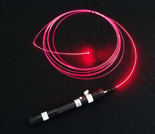
Using red laser light (a VFL here but a laser pointer works
also) to show how fiber guides light.
FOA has begun developing a series of YouTube videos intended for
teaching students in elementary, middle and high schools about
fiber optics. The first FOA video is titled "Fiber
Optics For Teachers." With this video, we show teachers
how fiber works and carries signals and then explains simple
experiments to demonstrate how fiber optics works in the
classroom using some plastic fiber and a laser pointer. Since
many teachers do not know where to get the fiber, the FOA offers
to send them a sample for use in demonstrations in their
classroom (USA only right now.)
At the end of the video, teachers are given directions on how to
request samples of the plastic fiber from the FOA.
This video joins the "Fiber Optics Live" series How
Light Travels In A Fiber, Fiber
Attenuation and Connector
Loss that show how fiber works using simple experiments
that can be duplicated in any classroom. More videos will be
coming soon.
If you have kids or know some teachers who would be interested,
please send them to the introductory video Fiber
Optics For Teachers and we'll be glad to help them
get started with some entertaining programs for their
classrooms.
Resources
For Teachers In K-12 And Technical Schools
Teachers in all grades can introduce their students to fiber
optic technology with some simple demonstrations. FOA has
created a page for STEM or STEAM (science, technology,
engineering, arts
and math) teachers with materials appropriate to their
classes. Fiber Optic
Resources For Teachers.
If
you have kids in school or know teachers who are interested,
send them to the FOA page Fiber
Optic Resources For Teachers.
Should
Your Company Become An FOA Corporate Member?
As all FOA
individual
members know, they join the FOA by becoming certified,
mostly taking their CFOTs but some CPCTs, either by
attending a FOA approved school or joining directly based on
field experience (our "work to cert" program.) Over the years,
we've been contacted by manufacturers, contractors, consultants,
and other types of organizations who ask about becoming members.
We don't certify companies or organizations, we told them, so we
were not sure what we could offer as a benefit of membership.
But then, companies asked about using our educational programs
to train employees, how they could get listed on the FOA website
as service providers or if they could get a quantity discount on
membership or certification for all the FOA members working for
them. That began to sound like a benefit for being an FOA
corporate member. And providing a list of useful suppliers to
the market could be a benefit to the industry as a whole.
So FOA has quietly been letting companies and other
organizations join the FOA to take advantage of those benefits
so we now have several hundred corporate members. We've put then
into a database and listed them on the FOA website in map
and list
form. Here's the map.
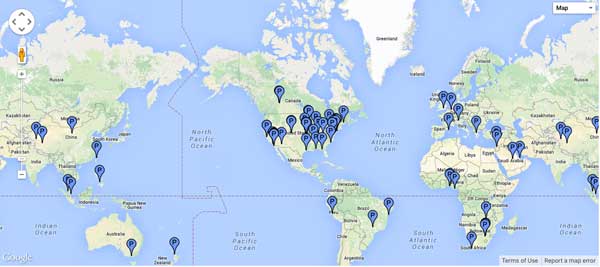
The online map
and list
can be used to find suppliers and service providers.
The map, like our map of schools, lets you find the FOA
corporate members close to you. The table form lists them
by category: Installer/Contractor, Component Manufacturer,
Installation Equip. Manufacturer, Transmission Equipment,
Services/Consulting, Distribution and Users of Fiber Optic
Networks. You can sort the tables to find members meeting your
needs, e.g. by location, certifications offered, etc. Click on
any column heading to sort that column; click twice to sort in
reverse order.
How
Does An Organization Become An FOA Corporate Member?
Simple,
just fill in the online
application form. When your application is accepted, you
will be asked to pay the membership fee - $100US first
year, $50US/year or $100US/3years to renew. You will then be
listed on the online
map
and list,
have access to exclusive FOA educational materials for your
employees and get discounts on certifications and
renewals.
Safety
On The Job


Safety is
the most important part of any job. Installers need to
understand the safety issues to be safe. An excellent guide to
analyzing job hazards is from OSHA, the US Occupational Safety
and Health Administration. Here
is a link to their guide for job hazard analysis.
FOA also has lots of information on safety: FOA
Guide, YouTube
video and a Safety
Poster
"Worth
Reading" Is Now On
Join
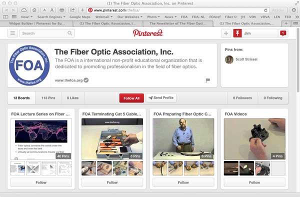
FOA on Pinterest.
We have been posting links to pages "Worth
Reading" on a special FOA Pinterest page. You can join and
keep up to date with the news on our industry which we put
there.
Recent
posts cover utilities using new generation telecom, India's
plan for 100 smart cities, Cincinnati Bell bets on fiber,
various opinions on the US battle over net neutrality, etc.
Good
Practice Tools For OTDRs, All Free
FOA
OTDR Simulator
You
may already know that the FOA has a free OTDR Simulator you can
download from our website (go
here for directions) that allows you to practice using an
OTDR on your PC (Win XP or 7), seeing the effects of changing
setup parameters and analyzing dozens of real world traces. But
here are two more tools that can be good for practice.
OTDR
FAQs
Including
more hints from FOA Master Instructor Terry O'Malley like tests
on what the end of a fiber trace looks like with broken and
cleaved fibers.
Frequently
Asked Questions On OTDRS And Hints On Their Use
"Fiberizer"
APP Reads, Analyzes OTDR Traces
Fiberizer
is a iPhone/iPad APP that reads industry-standard ".sor" format
files and allows trace analysis on your iPhone or iPad. An
android version is in the works too. Read
more about Fiberizer. And
here are more directions on its use.
Events of
Interest
FOA
now posts events on our LinkedIn groups, Facebook page and
other social media

FOA
has a company page and three LinkedIn Groups
FOA
- official company page on LinkedIn
FOA
- covers FOA, technology and jobs in the fiber optic marketplace
FOA
Fiber Optic Training - open to all, covers fiber optic
technology and training topics
Grupo
de La Asociación de Fibra Óptica FOA (Español)
RETURN
TO INDEX
 What's
Happening @ FOA What's
Happening @ FOA
FOA
Standards:
FOA now offers free standards for datalinks and testing the
installed fiber optic cable plant, patchcords and cable, optical
power from transmitters or at receivers and OTDR testing. Look
for the "1
PageStandard" web page and in the FOA Online Reference
Guide.
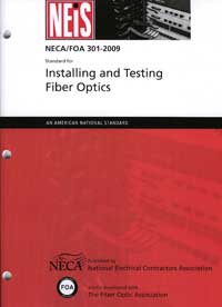
NECA/FOA
301 Fiber Optic Installation Standard
Standards
cover components and systems and how to test them, but rarely
get into installation issues. The FOA NECA 301 standard which
covers installation of optical fiber systems has been revised
for the second time, adding considerable new materials. This
standard is derived from FOA educational material put in
standards form and approved by ANSI as an American National
Standard. It's specifically written to be used in contracts to
define "installation in a neat and workmanlike manner." The
standard is available from NECA.
FOA members can go
here for instructions on how to download your free copy.
RETURN
TO INDEX
Free
Fiber U Self-Study Programs
FOA's
"Fiber U" free online self-study programs help you learn about
fiber optics, study for FOA certifications or use them to help
create "blended learning" classes. There are two new free online
self-study programs on Fiber
U. Fiber Optic Network Design is for those interested in
learning more about how to design fiber optic networks or
studying for the CFOS/D certification. FTTx is for those wanting
to know more about fiber to the "x" - curb, home, wireless, etc.
- or studying for the CFOS/H certification.
Got to Fiber U
for more information.
Fiber U
Online Self-Study Programs Offer Certificates of Completion
FOA has
been offering quite a few free online self-study programs on Fiber
U, our online learning site. We are always getting
questions about getting a certificate for completing the course
online, so we have setup an option to take a test online and get
a certificate of completion for these online courses.
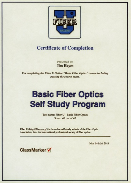
While it's not FOA certification, FOA will recognize a Fiber
U Certificate of Completion as background experience to
qualify for applying for FOA certifications. We also intend to
expand the program to more specialized topics as preparation
for FOA specialist certifications.
If you have associates that want to get started in fiber,
have them take this course online to get started. Go to Fiber
U and get started.
FOA
Books And Publications
FOA
Basic Fiber Optic Textbook Now Also Available in French
and Spanish


FOA
Reference Guide To Fiber Optic Network Design And FOA's
Outside Plant Fiber Optic Construction Guide

Read
More about the FOA
Reference Guide To Fiber Optic Network Design
and
More
information on the FOA
Outside Plant Fiber Optics Construction Guide
Lennie
& Uncle Ted Guides - Perfect For Getting Started
Lennie
and Uncle
Ted's Guides have moved to the FOA website.
Lennie is the place where many if not most fiber techs
begin their education. FOA has just updated the two
guides to ensure they stay relevant - more than 20 years
after they were first written.
Lennie goes all the way back to 1993 when he was created
as the mascot of the original "Fiber U" conference - the
same Fiber U that is now the FOA's web-based training
site. Lennie
Lightwave's Guide To Fiber Optics was created
as a beginner's introduction to fiber optics. Over
60,000 printed version of Lennie's Guide were given away
and it became one of the first commercial web pages in
1994. Uncle Ted's
Guide To Communications Cabling was written a
few years later to introduce techs to "Cat 5" - UTP
wiring - that had only recently been standardized in
TIA-568.
Lennie and Ted's Guides are used in the current Fiber U
online self-study programs and are still the best place
to start learning about fiber optics.
Lennie
and Uncle
Ted's Guides are online at the links here, can be
downloaded as printable PDFs and are now also available
as free iBooks on iTunes.
Lennie
Lightwave's Guide to Fiber Optics and
Uncle
Ted's Guide To Communications Cabling
are now available free to iPad users who can download them from
the Apple iTunes store. Of course they are still available
online or for download.
You can also find these free guides on the FOA website - go here
for all the links: Lennie
Lightwave's Guide to Fiber Optics and Uncle
Ted's Guide To Communications Cabling
Download PDFs of Lennie
or Uncle Ted.
RETURN
TO INDEX
FOA
iPad Apps
FOA
LossCalc
 FOA
LossCalc estimates the optical loss of a fiber optic link. This
will save time for the installer of a fiber optic link needing
to know whether test results are reasonable and/or make a
"pass/fail" determination. It can also help the designer of a
link to determine if communications equipment will operate over
this link. FOA
LossCalc estimates the optical loss of a fiber optic link. This
will save time for the installer of a fiber optic link needing
to know whether test results are reasonable and/or make a
"pass/fail" determination. It can also help the designer of a
link to determine if communications equipment will operate over
this link.
By choosing the type of link (singlemode or multimode) and
specifying the length of the fiber and numbers of connections
and splices, it will calculate the end to end loss of the link.
The app has default specifications for singlemode and multimode
links or the user may create custom setups with specifications
appropriate for any application. http://itunes.apple.com/us/app/foa-losscalc/id476262894?mt=8&ls=1
Self -Study in Fiber Optics
 Our
first app is a self-study version of the FOA Reference Guide to
Fiber Optics. The FOA APP builds on the FOA basic fiber optic
textbook to create an interactive learning environment that
builds on the iBook electronic version of the book to add a
guide to use for self-study and real-time testing that provides
feedback on what you have learned and correct answers to
questions answered incorrectly. Our
first app is a self-study version of the FOA Reference Guide to
Fiber Optics. The FOA APP builds on the FOA basic fiber optic
textbook to create an interactive learning environment that
builds on the iBook electronic version of the book to add a
guide to use for self-study and real-time testing that provides
feedback on what you have learned and correct answers to
questions answered incorrectly.
The FOA APP is priced at only $9.99, same as the iBook, so the
self-study program is free. Download it from the Apple APP Store
with your iPad or iTunes.
http://itunes.apple.com/us/app/foa-guide/id434354283?mt=8&ign-mpt=uo%3D4
RETURN
TO INDEX

The
FOA has many videos on  ,
including two Lecture Series (Fiber Optics and Premises
Cabling), Hands-On lectures on both and some other informational
and instructional videos. For all the videos, go
to the FOA Channel "thefoainc" or use the direct links
below. ,
including two Lecture Series (Fiber Optics and Premises
Cabling), Hands-On lectures on both and some other informational
and instructional videos. For all the videos, go
to the FOA Channel "thefoainc" or use the direct links
below.
View
a complete list of FOA Videos with links to each video on
YouTube.
Where Are
The Jobs In Fiber Optics? FOA talks about all the
applications for fiber optics, what jobs involve and the
qualifications for the workers in the field.
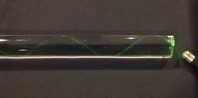
Fiber
Optics - Live! A
series of videos that use lab demonstrations to show how
optical fiber works.
Cabling
Project Management - what's involved in a
copper/fiber/wireless project -advice for the customer and the
contractor
Hazards
Of Counterfeit Cable
You may
have read the stories we have written about the counterfeit
"Cat 5" cable made from copper-clad aluminum rather than pure
copper. Recently we tried an unscientific burn test on the
cable compared to a known good UL tested cable and posted a
video on YouTube. You can see the results below.
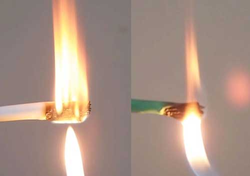
Counterfeit
Cable Real UL-rated cable
The
difference is obvious and the danger is real. Watch the video
on YouTube: Premises
Cabling Lecture 11: Counterfeit Cat 5 Cabling
View a
complete list of FOA Videos with links to each video on
YouTube.
View
all the FOA Channel on YouTube.
RETURN
TO INDEX

What's
New in the FOA Online Fiber Optic Reference Guide?
We are
continually updating the Online Reference Guide to keep up with
changes in the industry and adding lots of new pages of
technical information. Go to the FOA
Guide Table of Contents to see the latest updates - look
for  . .
Find
What You Want Using "Google Custom Search
 There's
so much information on the FOA Tech Topics and Online Fiber
Optic Reference Guide that even a well-organized Table of
Contents isn't enough and when the material is always changing,
an index is impossible to maintain. So the FOA is using the
latest technology in search, Google Custom Search, which will
allow you to search just the FOA Tech Topics and
Online Fiber Optic Reference Guide for any topic you want to
find more about. Try
it! There's
so much information on the FOA Tech Topics and Online Fiber
Optic Reference Guide that even a well-organized Table of
Contents isn't enough and when the material is always changing,
an index is impossible to maintain. So the FOA is using the
latest technology in search, Google Custom Search, which will
allow you to search just the FOA Tech Topics and
Online Fiber Optic Reference Guide for any topic you want to
find more about. Try
it!
Go
to The
FOA Online Fiber Optic Reference Guide.
RETURN
TO INDEX
New
Schools
The FOA welcomes the newest additions to our listing of FOA-Approved
Training Organizations:
The FOA network of training
organizations offering CFOT (and more) certifications continues
to expand. We welcome six new schools from quite different
backgrounds - a manufacturer, an electrical JATC and several
independent trainers.
Affiliate
School:
Capital
Commitment of Virginia, Fairfax VA
The FOA Fiber
U Affiliate program is for non-commercial schools
which wish to offer training in fiber optics or premises
cabling without offering certifications. Typically this
involves technical high schools or colleges offering telecom
or IT programs where the school would like to have a
curriculum module on cabling infrastructure which is usually
missing from these subjects. It may also be appropriate for
job retraining programs.
Find a listing
of all the FOA-Approved schools here.
Find An FOA-Approved Training
Organization
Most
inquiries we get regarding finding a FOA-Approved training
organization want to know two things: what school is closest to
me or what school offers the certifications I need. The FOA has
about 200 training organizations we have approved worldwide so
finding the right one can be difficult! We've been looking at
ways to make it easier, and we think we've got a good solution.
In fact we have two solutions.
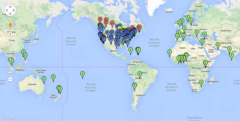
First we have added a sortable
table of all the FOA-Approved schools.
You can also use our FOA
Google Map to find FOA-Approved schools.
What
Should A Fiber Optics or Cabling Tech Know and What Skills Do
They Need?
FOA
certifications are based on our KSAs - the Knowledge, Skills and
Abilities that techs need to succeed. Read the FOA KSAs
for fiber and cabling techs.
School News
Feedback
We always
enjoy feedback, especially when it shows how great some FOA
instructors are. These came from students of Tom Rauch, an
instructor at BDI
Datalynk:
"I took your fiber optics certification courses this past March.
I just wanted to let you know that in two weeks I start working
as a fiber optic technician with ___ up in ___. You mentioned on
the first day of the course that there is always one guy in
class who had rubbed his last two nickels together to be there
and, in that instance, I was that guy. Now I'm going to be able
to provide for my family like never before and I owe it to the
certification that I received from you and BDI Datalynk. I just
wanted to thank you again."
"Thanks to our tremendously knowledgeable and patient instructor
Thomas Rauch, who was not only generous in sharing his wealth of
information, but he did so with ease, humor and in a way that
invited curiosity and participation. He was encouraging and
proud of our accomplishments and helped us learn from our
mistakes in a way that did not break our confidence, rather it
pushed us to better results the next go around. The hands on
labs were just AWESOME!" Just thought you should know what a
class act you have representing you in his travels..... but then
again you probably already knew that! : )
In almost 19 years at Verizon and having held numerous
positions, I have gone through many training sessions. I cannot
remember ever having been actually looking forward to coming
back to class quickly after lunch, to get back to the hands on
activities, and walking away with the sense of empowerment that
the information presented was not only relevant but dead on
point accurate! I will be signing up for the Outside Plant class
on March! I can't say enough good things about Tom and his
impact! Feel free to quote me, I can only imagine that he will
open so many doors and change so many lives in the years to
come, with his style of teaching! Great experience, awesome job!"
IBEW
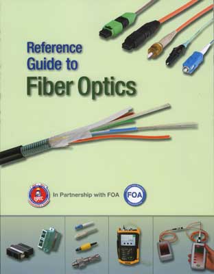
and FOA Partner on Fiber Optic Training
The
International Brotherhood of Electrical Workers (IBEW) and the
National Electrical Contractors Association(NECA) through the
National Joint Apprenticeship and Training Committee
(NJATC) in
a partnership with the FOA has published a new textbook for
training IBEW apprentices and journeymen in fiber optics. The
new textbook uses the material from the FOA Reference Guide To
Fiber Optics with new material and photos from other NJATC
training partners.
Quote
from one of our certified instructors: I want to thank
you and your organization for all the resources you provide for
the students and the opportunity to offer the certification to
the students. The fact that you published the book yourself to
get the cost down and the unlimited free resources on your
website shows a commitment to the public that is second to none.
I let it be known to the students that the FOA is the best in
the industry at supplying knowledge and resources related to the
communication industry. I look forward to passing on the
information that you provide for the industry.
RETURN
TO INDEX
Good
Question! Tech Questions/Comments Worth Repeating
Real
Questions From FOA Newsletter Readers
Terminate All Fibers Or Just Some?
Q:We
are currently running fiber which will be 12/24, my question is
do we need to terminate every pair even if we aren't going to be
using them or is there an alternative?
A: No
you do not need to terminate all of them and leaving some bare
fibers is often done when there is no planned use for the fibers
or to save money. However, there are some other issues to
consider. You do need some spare fibers ready to use, either in
case of problems or for upgrades. For small fiber counts, the
cost of terminating them all at once will be cheaper than having
to come back to the site and doing it in the future. The
economics are quite different if you have 144 or more fibers, of
course. If you leave bare fibers, be sure to leave enough length
to terminate or splice later - about a meter for termination and
2m for splicing. And protect them from damage so they can be
used in the future.
OTDR
Calibration
Q: I know user who want to send their OTDR’s in for
calibration, especially those that do government work. Are
you aware of a check list of the required tests to comply to
what would amount to an “OTDR Calibration”?
A: ORDR calibration is covered on FOA
Guide page on OTDR FAQs - OTDR calibration is
a unsolved problem. I was first involved with it at NBS in
Boulder (now NIST) in the mid to late 1980s. They could not
justify having a set of “golden fibers” to send around because
they could not figure out how to make a “better" OTDR to use as
a standard as we/they did on fiber optic power meter
calibration.
Later some tried building electronic calibrators that could
calibrate the timebase and linearity of the receiver, but that
ignored the laser transmitter - you would need to calibrate it’s
wavelength also. Wavelength variation could cause up to 3%
difference in backscatter and loss measurements alone. Then the
OTDR allows for changing the index of refraction to different
fibers which affects length measures.
At one time some manufacturers looked at OTDR cal systems but
the only electronic cal units for OTDRs I know that made
production came from Belarus. There is a single system in the
Navy at Corona, CA however.
Bottom line, test it’s operation according to manufacturer's
spec.
Variations In OTDR Length Measurements
Q; I am performing OTDR testing using 3 different
wavelengths (1310, 1550, and 1625) on the same fiber but I get 3
different results for fiber length. The test set and
testing parameters do not change.
A: The OTDR calculates length by measuring the transit
time to an event (half the total time since it measures the
pulse time both down and back) and multiplies it by the speed of
light in the fiber. Speed = C(speed of. Light in a vacuum)
divided by N(the index of refraction of the glass). Most fibers
have an N~1.46.
In an OTDR that speed of light is set using index of refraction
in the setup parameters. In the fiber, the light actually
travels at different speeds according to the wavelength of light
- that is what causes chromatic dispersion. For Corning SMF -28
SM fiber, effective refractive index at 1310nm is 1.4674,
and at 1550nm is 1.4679, not much difference but adds up at 10km
or more.
So your OTDR probably has the wrong setup.
Connector Mating Adapters
Q: I am looking for a standard that describes the value of
parameters (IL, RL) and class (if we can talk about class) for
FO mating adapters.
A: Mating adapters are part of the connection but like
each connector they only contribute to the total loss of the
connection and cannot be separated from the other two when
talking about loss. They can be specified by mechanical
dimensions and materials. For example on 2.5mm ferrule
connectors (SC, ST, FC and the obsolete FDDI and ESCON duplex
connectors) the mating adapters have had alignment sleeves made
of molded glass-filled thermoplastic, phosphor-bronze and
ceramic. The plastic ones are cheap but wear out quickly - 10
insertions will leave plastic dust all over the mating
connectors. Phosphor-bronze mating adapters last longer - maybe
500 cycles. The ceramic sleeve ones last almost indefinitely. We
know this because we were in the test equipment business for 20
years (we started FOTEC in 1980 and sold it to Fluke in 2000)
and we tested these mating adapters for longevity with reference
test cables used in insertion loss testing. We had many calls
from techs with problems caused by the adapters with plastic
sleeves. So the way we know the mating adapters are graded is by
alignment sleeve materials.
Removing Old Fiber
Q: I have several 1000 feet of old 62.5/125 armored fiber
optic trunks under a raised floor that I am replacing/upgrading
to 50u MM and SM trunks. Is there any guidance on ‘Best
Practices’ to follow when cutting these trunks into more
manageable lengths for removal?
A:
Use a jaws-type cutter to cut the cable into reasonable lengths
and remove it. There should be no danger in cutting the cable up
as long as your workers only cut the right cable. Raised floors
often have large numbers of cables - often including power
cables - so its important to ensure the proper cables are being
cut an removed.
APC Connectors
Q: With a fiber optic pathway that has multiple patching
points...if the end user requires APC connections, isn't it only
important to have those angled connectors at the end/equipment
connections with UPC being acceptable throughout the middle part
of the link?
A:
Reflectance at the connection is the issue, of
course.
Reflectance near a transmitter can affect the laser transmitter
causing nonlinearities or noise in the device. That’s always
been a major concern.
The second issue is reflectance causing background noise in the
link. If you have ever seen a ghost on an OTDR, you have seen a
reflectance at a connection that is bouncing back and forth in
the fiber and is of high enough amplitude that you can see it at
the source. Of course if it reflects back and forth in the fiber
link, it will also show up at the receiver end, becoming noise
and/or distorting the receiver pulses. In a bidirectional
single-fiber network like a PON, it affects receivers at both
ends.
Some refer to this as multipath interference. It is being
studied by international standards groups but nothing has been
published on it as far as I know.
We are familiar with a link that was ~1km of SM fiber with
hand-polished ST connectors at several connections. The link had
acceptable loss for all the fibers in the cable but none would
work with electronics. Replacing the connectors with fusion
spliced pigtails cleared the problem up immediately. Was the
problem
With that background, I would answer you question this way. APC
connections at each end of the link will effectively stop any
reflectance issues going back and forth in the whole link. Using
UPC or PC connectors in the link with reflectance better than
-40dB are unlikely to cause problems. (Keep them clean of course
since dirty connectors show high reflectance.) If the links are
very short (<1km), the fiber will not attenuate any
reflectance substantially, so short SM links (FTTH and passive
OLANS for example) often use APC connectors everywhere.
And a final practical issue - mixing APCs and PC connectors is
very bad, perhaps damaging the surfaces. If you do mix them in a
link, you must train personnel how to handle them. If you have
patch panels with PCs and equipment with APCs, for example, you
have to ensure the patch cords are color coded properly (blue =
PC, green = APC) and everybody knows not to mix them
What Do Testing Results Indicate?
Q: I was told the other day by a network technician that
it is possible that a fiber optic strand that is tested to
standard, 850, 1300, mm and 1310-1500 SM bi-directional can pass
a test but when connected to an optic it doesn’t work. I told
him that the optic is the variable but if a strand passes the
testing its qualified to “work” or pass light.
A: There are several reasons it can be true.
Either MM or SM
-The installed cable plant is OK but the patchcords are bad. Or
mixed up - we know instances where systems did not work because
MM systems were connected with SM patchcords and vice versa -
instant 17-20dB loss.
-The polarity is wrong so the transmitter does not go to the
proper receiver. For MPO networks, this is a major problem since
there are so many different polarities used. (See MPO
array/parallel connectors and how to test them). This is often a
documentation problem.
-Post testing, the connectors get contaminated and not cleaned
or are damaged.
MM
-The link meets the loss budget but the length is too long for
the fiber type to support the transmission bit rate - e.g. OM2
fiber on a 10G system that is near 300m long (see
Specifications for fiber optic LANs and Links for the list of
lengths supported)
SM
-Mixing PC and APC connectors. Bad for loss - may cause serious
damage too.
-Reflectance problems. Interestingly this question was asked
this morning by the tech boss at a giant university. Here is the
question and my answer:
Connector Loss At Patch Panel
Q: If I have two SC connections in a cabinet eg one
incoming cable jumperd to an out going cable. Should I be
looking for a loss of no more than .75db across the two of them
as per TIA-568
A:
TIA 568 has included a connector loss of 0.75dB for decades.
Even the committee is aware that this is a bogus number for most
connectors but they leave it in because the manufacturers of MPO
connectors need it to comply with the standard.
SC connections should be ~0.2-0.3dB if the connectors are good
and properly cleaned. Now in the patch panel you describe, each
of the two connections should be in that range for a total loss
of 0.2-0.6dB. TIA would allow 0.75dB for each connection or
1.5dB total.
Differences In Fibers
Q: What is the difference between OM3 and OM4 type fibers
and G.654/G.655? They seem to be rated for the same amount
of GBs (10-400) and the only difference seems to be the
multi-mode nature of OM3/4 vs. the single mode nature of
G.654/655. Can they both be used in long haul communications if
laser optimized?
A:
OM3 and OM4 fibers are both 50/125 micron fiber but have
different bandwidth capability. OM3 is rated at 1500MHz-km while
OM4 is rated 3500 MHz-km. OM4 is an evolution of OM3 where
design and manufacture allow more bandwidth. More bandwidth
translates into slightly longer link lengths in faster networks,
~1-10Gb/s. For example, Ethernet at 10Gb/s will go 300m on OM#
and 450m on OM4, which can be important if it is being chosen
for a enterprise network backbone.
The differences in G.654 and G.655 are more complicated. G.654
is singlemode fiber optimized for use at 1550nm for long
distance use. G.655 is “non-zero dispersion shifted” fiber
tweaked for dense wavelength division multiplexing (DWDM) to
prevent secondary problems with high power and closely spaced
wavelengths of DWDM and fiber amplification. It’s the kind of
fiber used in long submarine cables.
From
Feb 2018
Testing At 820 or 850nm
Q: I
am working on calibration of an optical power meter. It is an
old Photodyne 2285XQ and I need to test it at 820nm, I believe
this wavelength is (or used to be) fairly common in military
applications. The problem is the only equipment I have available
is all based around 850nm/1310nm/1550nm. Our optical power
meters and optical spectrum analyser can certainly operate at
820nm, but I’m having real difficulty finding a commercially
available light source at 820nm.
A: That Photodyne meter was probably built before the US
National Bureau of Standards agreed around 1983 to create the
first calibration standards for fiber optic power meters. NBS
created standards for the three primary wavelengths of fiber
optics - 850, 1300 and 1550nm - based on the available laser
wavelengths for calibration with their standard ECPR -
electrically calibrated pyroelectric radiometer. The 850nm
range was never considered a problem because in the early days
LEDs were sometimes called 820nm and sometimes called 850nm, but
the spectral width is quite wide and the variation in actual
peak wavelength, even as called out in standards, is 850+/-30nm
or 850+/-20nm, making it a very “broad” standard.
I know the rules for MIL standards and calibration so here are
several solutions. Your solution will require a transfer from
some transfer standard power meter.
1. Use the 820nm laser and calibrate the output with the H-P set
at 820 if that is possible. Possible error due to calibrating
only a small spot on the Photodyne detector.
2. You can also make the cal above with a high-intensity source
with a filter around 820nm.
3. Use an 850 LED and calibrate the output with the H-P set at
820 if that is possible. This assumes the photodetector
sensitivity curves are similar.
Negative Loss?
Q: We
were sent this OTDR trace and asked why some traces showed
negative loss - gains.

A: The
issue with this OTDR test of a factory-manufactured patchcord
was not straightforward. To summarize, the patchcord was plugged
directly into the OTDR port, with no launch cable. The OTDR has
no reference for measuring the loss of the first connector on
the cable nor the second connector since neither launch or
receive cables were used. Without a launch cable, the OTDR is
trying to get information from the connection to the instrument
itself which is basically impossible since it’s suffering from
overload caused by the test pulse - even with APC connectors.
The OTDR (Yokogawa) is one of the cleanest OTDRs at the
interface (we have one on loan at FOA right now) but it’s still
not designed to measure that loss. Furthermore, using the
instrument interface to plug in every connector will wear that
connector in the unit out quickly and require servicing by the
factory. The second issue is the difficulty of measuring on
short cables like this. Note the vertical digital resolution of
the display and think about the location of the second marker -
it’s measured dB value will jump around as it goes from digital
segment to the next digital segment. When you use a launch cable
and measure the loss of the connectors using the “4-point”
measurement - also called “least squares approximation” in the
FOA Guide to OTDRs. That will overcome the digitization errors
as well as the settling times of the pulses.
POTS over Fiber
Q: I would like to know if there is information on your
website that explains "POTS OVER FIBER"?
A: POTS - the acronym for “plain old telephone service” -
is digitized to transmit over fiber. In the early days (late 70s
and 80s) it was simply T-carrier with a fiber converter. By the
end of hte 80s it was ATM and SONET. More recently, it’s all
going to carrier Ethernet since 99%+ of the traffic is data not
voice or PONs (passive optical networks) for fiber to the home.
Re-routing Old Fiber Optic Cables
Q; I have a questions about the re-routing of fiber optic
lines that have been in place for a number of years. Is it
a standard transaction in the fiber optic business to have to
re-route fiber that has been in service for a long period of
time. (e.g. >20 years) If so, is there a best
practice for removal from conduit for re-rerouting?
A; There is no way we would recommend removing and
reinstalling 20-year old fiber cable. First of all, old cable
may be damaged in removal. Then cable and fiber technology has
improved over the years so you can get much better components
today at greatly lower prices. (One industry analyst I know
likes to say that fiber is cheaper than kite string and fishing
line!) Today’s cable designs allow for much smaller cables with
many more fibers (288 fibers in 9.7mm - just over 3/8”) and new
conduit designs allow for more cables in a conduit (microducts
and cloth ducts) and easier installation - blowing in cables and
microtrenching are perfect for metro areas.
More fibers, especially in a big city, is a must. Smart cities,
small cells, FTTH (fiber to the home), ITS (intelligent traffic
systems), V2X (vehicle to vehicle, infrastructure, etc.) and
many other services need lots of fibers.
Our recommendation is to pull it out and dump it. Install new
ducts and the fiber you need (x10 maybe?) and have new ducts for
future use. Are you familiar with “Dig Once”?
APC Connectors On Power Meters
Q: We need to test a fibre link terminated with APC SC
pigtails. I am using SC-APC Ref Leads to interface the LSPM to
the fibre link. I am using the 1 Test Cord Method. Step 1 means
connecting the LS to the PM via one Ref Lead. That means I have
an APC Green SC connector plugged into the PM. Is that
OK?
A:The SC APC connector should only be mated to another SC
APC connector to prevent potential damage to the fiber/ferrule
end. But most power meters have adapters for the connector that
have an air gap above the detector to prevent contact to the
detector window. Plus, the detector should be large enough to
capture the light from the SM fiber exiting at a small angle.
Thus you can plug the connector into the power meter directly.
Some meter manufacturers make SC APC adapters for their power
meters that angle the connector toward the detector but that is
generally not necessary unless the meter has a very small
detector.
However if the power meter has a pigtailed detector - that is
the meter has a fiber>fiber interface, you will need to add
an adapter patchcord to mate the APC connector to it. When you
set a 0dB loss reference all those connections will be zeroed
out.
Directional
Testing
Q: I have taught for several institutions and throughout
all my years of doing this I was always taught that when testing
for insertion loss and back reflection for singlemode cable
links that testing bi-directional is an imperative.
Recently when I was attending a meeting involving members of the
military along with folks involved in the development of the
military manuals, it was mentioned that with singlemode testing
that bi-directional testing is not necessary.
A; First of all, there is a directional difference in
splice or connector loss - and maybe reflectance (that term is
now almost universally used in place of “back reflectance” which
is a poor term since a reflection is always back) - as long as
two different fibers are being spliced. Fiber geometry is the
main difference - mode field diameter in SM and core diameter in
MM - but it can also be a matter of the fiber composition.This
happens if two different manufacturers’ fibers are joined or
bend-insensitive (BI) fiber with differences in depresssed
cladding geometry are joined.
If you test bidirectionally with sufficient accuracy, you can
see the difference. It’s an OTDR trace that most people are
familiar with - if you see a gainer, you shoot the
other direction and average to get the “actual” splice loss.
When splicing or connecting different types or manufacturers SM
fiber you may see directional differences of up to 0.3dB or
more. Same for MM, not only for differences in core diameter but
also for connecting BI to non-BI fibers. While those OTDR
measurements are actually differences in backscatter levels,
they are indicative of real differences in connector loss or
splice loss in opposite directions.
Are those differences enough to be of concern? That’s a judgment
call.
We’ve found most people do their bidirectional testing all
wrong. With an OTDR, you should disconnect the instrument, not
your launch and receive cables, and take just the instrument to
the other end. Disconnecting the launch and receive cables
changes the fibers at the connections to the cable under test
and you lose the connection you want to test from the opposite
direction.
Bidirectional testing with a test source and power meter is more
confusing. You have to do your “0 dB” reference, check the
launch and receive reference cables, measure the cable under
test, then move just the source and meter to the other end, test
the cable under test again, then disconnect and then measure the
output of the source to get the “0 dB” reference used in that
direction. That’s confusing!
Even if you do test bidirectionally, you do not get the “actual”
connection or splice loss like everybody says - you get the
average of the two directions. Unless you are willing to do a
lab setup and some careful testing, that’s the best you can do.
Now we are into measurement uncertainty. If the measurement
uncertainty is around the same as the typical bidirectional
difference, does bidirectional testing gain you that much?
That’s a judgement call.
The new FOA book on
testing goes into this - a complete chapter is devoted to
measurement uncertainty.

When To Test Fiber
Q: Should testing of the fiber plant be done before the
Optical Network Terminal is installed?
A: Fiber optic testing is generally done when the cable
plant is installed to confirm proper installation and check that
the performance is adquate for the electronics planned for use
on it.
There are several processes - first an overview of testing:
Check cable before installing - continuity if it looks OK, OTDR
testing if the reel is damages
Test installed cable when splicing - check the fusion splicer
estimate of loss and do OTDR testing if questionable and inspect
every connector as termination is done to confirm the connector
is good.
Test cable plant after splicing and termination - end-to-end
insertion loss and OTDR testing for longer OSP (outside plant)
links.
New singlemode cable plants for high speeds may need "fiber
characterization” - adding in CD (chromatic dispersion), PMD
(polarization mode dispersion) and SA (spectral attenuation for
DWDM wavelengths) testing. If one is considering upgrading a
cable plant that is already installed or has been used, these
same tests should be done - inspection/cleaning, insertion loss,
OTDR.
When the system is installed, one should know it should work
because of the testing done during installation. One should
inspect and clean patchcords before installation and test them
if suspect. In fact any connector needs inspection/cleaning
before hooking up equipment. Dirt is the biggest problem with
fiber optic systems.
Differences
Between Singlemode or Multimode Mating Adapters
Q: What is the difference between singlemode and multimode
bulkhead/adapters (mating adapters). My understanding is you
cannot use the singlemode with the multimode and visa versa.
A: There are 3 types of adapters - rated for SM or MM -
based on the alignment sleeve material.
-Plastic (glass filled thermoplastic) alignment sleeves are
cheap, not very precise and wear quickly (you can see ceramic
ferrules get dirty using them) - only good for multimode and one
or two insertions - not recommended
-Metal (phosphor bronze) alignment sleeves are better with good
alignment but still wear some - OK for MM, some are rated for
singlemode (check before you buy), and are OK for most uses but
will wear out if used for repetitive testing
-Ceramic alignment sleeves are the best and most expensive. They
are very precise in alignment and last for a long time.
Recommended for all singlemode and all testing purposes.
Don’t use MM adapters for SM but SM adapters are OK for MM.
Why A Figure 8?
Q: What is the reason for wrapping the cable in a figure
eight?
A: When you need to do an intermediate pull, you have to
pull the fiber and coil it on the ground. A simple coil will put
a twist in the cable. Figure-8 coils put in twists of opposite
directions on each side of the 8 making for no overall twist in
the cable. See How
To "Figure 8" Cable For Intermediate Pulls in the FOA
Online Guide.
Can I Build A GPON Network With "Taps"?
Q: Can I build a GPON network where I do a drop to one
subscriber then continue to the next subscriber for another drop
and so on?
A: There have been examples of this type of “tap” drop proposed,
for example in rural areas for drops to widespread
subscribers on a longer network than is typical for FTTH. It’s
just a version of a cascaded splitter network. with taps that
just do a 2 way split. The taps used are typically 90/10 taps,
where 10% of the power is tapped off for the drop.
There are some important issues to consider - Since you are
dropping 10% of the power at each tap, you are limited by how
many drops you can have. If you calculate the loss
budget - after the first tap, you have 90% power left less the
excess loss of the splitter (~0.3-0.5dB). The tap power is down
~10.3 dB and the through power is down ~0.6 dB. At the next tap,
you use the same formula plus you add the loss of the
fiber to that tap and so on until you reach the GPON
limit. It’s a pretty complicated process to design, but
you can see that with these power losses you will not get a
large number of drops in a GPON network with 28dB max power
budget. We did a rough calculation and 20-24 drops may be
possible depending on the fiber lengths.
This network will probably be much more expensive and more
distance limited than simply running a cable with many fibers
and dropping fibers from that cable with midspan entry. Couplers
are expensive, fiber is cheap. We also do not know the issues
with the large differences in transmission times between the
first connections and the last ones, which depends on the length
of fiber in the systems. That may require some programming at
the OLT.
Replacing
OM1 MM Fiber
Q: We are an automation system integrator in South Africa. We
have a client that has multimode 62.5/125 fibre optic plant
wide. None of the runs between components are longer than 2km.
We intend to upgrade the technology from a proprietary
communication protocol to a standard ethernet protocol at 100
MHZ. The fibre to copper convertors we will be using are using
1300nm light source and have a Fibre Optic Link Budget of 12.8dB
for 62.5/125 um and 9.8dB for 50/125 um. The client has been
advised to replace the multimode 62.5/125 with multimode 50/125
cabling and we need to know if this is really a requirement.
A: Do you know how old the fiber is? It should be what we called
FDDI grade 62.5/125 fiber with a loss of ~1dB/km and a bandwidth
of 500MHz-km at 1300nm. A 2km link should have a loss of 2dB for
the fiber and ~0.5dB/connection - well under the power budget of
the link. 100Mb/s Ethernet variants were designed for 2km or
more on this fiber. There is no reason to upgrade at this time,
50/125 fiber would not be needed until Gigabit Ethernet was
desired.
Do We Need Repeaters For 30 Mile Link?
Q: I need to design a 30 mile (~50km) link. Will regeneration
like a fiber amplifier be necessary?
A: It depends on the comms equipment but I doubt you need
regeneration. 30 miles is 50km, only 10dB of loss for the fiber
at 1550nm, maybe 10 splices at <0.1dB adds only 1dB loss and
another dB for connectors on each end. I think you probably can
find equipment that runs on 12dB loss budget. That said, most
new high speed systems (>10G) have 20km versions then go to
expensive long haul coherent systems. So talk to the
communications equipment manufacturers and see what they say. If
you do need a EDFA, they are not that expensive but the site is
expensive and requires power (+ backup). See if it’s possible to
put the EDFA in the end facilities to get enough power for the
whole run.
Testing PCS Fiber
We Get Many Questions From Our Instructors Also
Q: I recently did a CFOT
training class for a government agency. They use 200
micron core fiber in short sections (50 ft. the longest) within
aircraft. The connectors are SMA 905s. The cable specs
state that there is 8dB of loss in 1 km at 850nm. I have
searched but cannot find any info regarding how to test the
cable/connector links. The OLTS they have uses 62.5/125
jumpers. Is testing these cables with the above OLTS setup at
850 nm a valid testing method?
A: That’s 200/240 PCS or HCS fiber - plastic clad silica or hard
clad silica step-index fiber - that has a glass core and plastic
cladding. It has been used on a lot of platforms because it’s
large core makes connection alignment easy. The SMAs are used
because the connectors are air gap connections so vibration will
not cause scuffing that you can get with PC - physical contact
connectors. On aircraft, the 1/4-36 nuts on the SMAs are usually
safety-wired too.
Testing can be done just like any other cable plant with a
double-ended test (OFSTP-14) for the whole cable or a
single-ended test (FOTP-171) to check the connection on either
end. You need a 850nm LED source and a meter with a large
detector (>2mm) to pick up all the light and an adapter for
SMA connectors. You also need launch and receive cables of
matching fiber and connectors about 2m long. No worries about
mode conditioning since the step-index fiber is a mode mixer
itself.
Fiber attenuation coefficient of 8 dB/km sounds about right.
Connection losses ~0.5-1.0 dB are normal. A typical patchcord
would have a loss of ~1-2 dB.
To get a microscope to view it might be difficult.
VFL
for 10km?
Q: I have
10 kilometers of singlemode cable installed that was not
labeled. It has been suggested that we shoot a VFL down the
fiber and label it. I am having trouble finding a VFL that will
shoot this far. Any ideas?
A: Occasionally we see some imported VFL that claims to go 10km
or more. That tells us the company is clueless about fiber
optics. VFLs work at ~650nm in the visible red spectrum while SM
is optimized for 1300-1600nm in the infrared where it has a loss
of ~0.3dB/km. At 10km it has a total loss of ~3dB or half the
input signal. At 650nm, singlemode fiber has a loss of ~10dB/km
which means it loses 90% of its power per km. At 10km, you have
100dB of loss - leaving you with 0.00000001% of the input power
- not much!
VFLs have enough power for 2-3km max. To identify fibers at
10km, you need a 1310nm laser source and a power meter to do
continuity. Or a gadget called a fiber identifier. For more
info, see
http://www.thefoa.org/tech/ref/testing/Instruments/instr.html
and http://www.thefoa.org/tech/ref/basic/test.html
Connecting
WiFi Access Points In a Passive Optical LAN
Q: If we
install GPON passive fiber optical LAN in a new hotel, would one
need to run fiber to every AP? Since every hotel room needs an
AP this gets expensive. Any suggestion on the simplest and less
expensive way of connecting Fiber Cable to an AP in the
hotel room?
A: You do not need a fiber to every wireless AP in a GPON
passive optical LAN (POL). The AP needs a UTP (Cat 5e/6) cable
with Gigabit Ethernet and POE (Power over Ethernet)
capability. The POL fiber should terminate in a multiport
switch that has a fiber input and then 4 or more UTP/POE outputs
for the wirelses APs. That’s the cost saving architecture of a
GPON POL. See this page in the FOA Guide:
http://www.thefoa.org/tech/ref/appln/OLAN-POL.html
You should also check out the APOLAN website (http://www.apolanglobal.org)
for more information on hospitality applications with POLs.
Wireless
Infrastructure
Q: I am
wondering how the landscape will change as the nation moves from
4G-LTE to 5G. Will it use the same network as currently, or will
the network need to be updated or replaced? To what extent will
5G be dependent on wireless vs fibre optic? Will the
infrastructure nationally move more toward an underground wired
one, rather than a Radio Access Network?
A: The wireless network is totally dependent on fiber optics for
it’s communications backbone. The “wireless” part is the
connection from an antenna to the mobile device. From that
point, the network is cabled, mostly fiber already and soon to
be all fiber.
4G/LTE and soon 5G in urban areas is moving to “small cells”
with about 10X as many cell sites covering much smaller areas.
Every small cell site needs a couple of fibers. Metro backbones
will require very much larger fiber counts, especially with
C-RAN (centralized radio access network) architectures now being
implemented.
An example is Santa Monic, CA where we live. It has about 200K
citizens, 8.9 square miles(about 23 sq km), but has planned for
600 small cell sites, spread over multiple service providers.
At FOA we see wireless as one of the most active areas for
fiber, along with data centers.See http://www.thefoa.org/tech/ref/appln/wireless.html
OTDR
Setup
Q: What are
good OTDR settings for a 300-500m fibers? We’re using a 1.5 m
launch cable and sometimes got (-) loss,
A 1.5m cable is not a launch cable. A launch cable must be long
enough to allow the OTDR to settle down after the test pulse.
THe negative loss is because the OTDR has not settled down
sufficiently.
Generally the minimum launch cable for testing short cables
would be 10-20m for MM, 100m for SM. Then use the shortest test
pulse, ~1km range, average enough to reduce the noise.
Arsenic
Coated Cable?
Q: I was told a contractor installed arsenic
coated fiber optic cable because they didn’t want animals to
chew through it. Is this true?
A: Some cable has
chemicals put in the jacket to make it taste bad to rodents. We
have not found any one who claims to use arsenic, in fact, we
could find no references to what kinds of chemicals are used.
Why
Do Cables "Go Bad"?
Q: It’s been my observation over ~15 years of building
and managing fiber channel storage area networks that from time
to time cables will fall out of transmission spec. In
terms of communicating with non-storage people, they in essence,
“go bad”. Other than possible damage due to physical
disruption of a cable, or contamination at the connectors
usually caused by a human being unplugging/replacing, has it
been your observation that MM cables can “go bad”?
A: There are some
possible causes of problems over time. We know of connectors
that fail for several reasons.
- The
biggest cause is with prepolished/splice connectors with
mechanical splices. the assumed problem is the index
matching get goes bad, but that’s highly unlikely. It’s
usually the crimp fails and the fiber pulls out, especially
if it has any stress on the fiber.
- Adhesive
connectors can have a bond between the connector and fiber
fail, more likely on anaerobic connectors.
- Any
stress on the fiber at the connector is bad. Patchcords
should not be left hanging on racks but dressed into
horizontal racks below each patch panel.
- Residual
stress in cables can be a problem - tension or tight bends -
and they may get worse over time.
- Moisture
is always a worry. It takes years to show up, but indoor
cables are not protected from moisture like OSP cables.
- Of
course, transceivers fail too - electronics are generally
very reliable but do deteriorate over time and cause
failures.
We always
say fiber requires no maintenance - set it up right and lock it
up. As you pointed out human intervention is often the issue.
Fiber
Ports Or Media Converters?
Q: Should I Buy A Switch With Fiber Ports Or Use Media
Converters?
A: I’m assuming you are
thinking of using a switch with copper Ethernet ports and a
media converter instead of a switch with fiber ports. The
downside is that it adds complexity and increases the chance of
failure. My analogy is something my primary flight instructor
told me many years ago - multiengine planes are not safer
because having two engines doubles your chance of having an
engine failure. IBM still says that most network problems are
cabling problems. Using media converters adds more electronics,
more power supples and more cabling connections.
Testing
PON Meters And Sources
Q: We're evaluating PON power meters and test sources.
How should we test them? Do we need a PON network?
A: There is no
requirement for having a PON to test the meters. I would check
it against a meter you trust to test
1) if the reading of absolute power (dBm) agrees - should be
within +/-0.2dBm. Compare at several power levels, as high as
possible (~0dBm with a laser), medium, (~ -20dBm) and very low
(~ -40dBm)
2) make some loss tests of cables and attenuators over the range
of 1-5-10-15-20dB and compare to a meter you trust.
3)the extra calibration at 1490 is not an issue - the difference
between 1490 and 1550 is very small and providing that
calibration can be more a confusion factor since there are no
transfer standards for that wavelength.
3) The big issue with sources is stability. Connect the source
with a short cable to a trusted power meter, connect it to its
power supply, turn it on and monitor the output over time. There
should be a short warm-up period and then it should be stable
within a few 0.01s dB. Let it run on batteries until the
batteries run down to ensure that the source has a proper power
supply that keeps the light output stable over time as the
batteries discharge.
High
Loss At 1383nm?
Q: We tested one link of 90.8 km at 1310/1383/1550nm
and we got high loss at 1383 while other wave lengths have good
results. What's up?
A: That wavelength is
the center wavelength of the OH+ water peak, so you are seeing
the extra attenuation there. Older fibers will have attenuation
of 2-3 dB/km at that wavelength but new “low water peak” fibers
will be <1dB/km. See “Low Water Peak Fibers” here http://www.thefoa.org/tech/ref/OSP/fiber.html
Polishing
Films
Q: Are there different grades (micron) polishing
films/papers for multimode and single mode fiber cables in ODF
termination ? If yes, What are the grades polishing papers for
multimode 50/125 um and 62.5/125 um fibers.
A: The polishing of MM
and SM fiber is indeed different. Both start with an “air
polish” with 12micron alumina polishing film to remove the
protruding fiber. Then the polishing continues on a soft
polishing pad (3mm 80 durometer rubber).
MM uses a 3micron alumina polishing film polished dry then a
final 0.3micron alumina film polish. See
http://www.thefoa.org/tech/ref/termination/ConnHints.html
SM is usually done with a wet polish using as special polishing
slurry and diamond polishing film. The diamond film will polish
both the ferrule and the fiber to get the best end finish. See http://www.thefoa.org/tech/ref/termination/sm.html
There are even more pages of information on the FOA Guide at http://www.thefoa.org/tech/ref/contents.html#Components
Armored
Indoor Cable?
Q: Can I get an indoor armored 8 core fiber optic
cable?
A: Most cable
manufacturers make indoor armored cable using corrugated wrap
armor to protect cables from crushing loads from other cables
especially in under floor installations.
MPO
Connector Loss
Q: Is there a current standard, for maximum allowable
loss, for MPO fiber connectors? If so… what is the standard #
from EIA/TIA? (Was it amended in 568B, since they were
introduced?) Would it be similar to standard connectors @ 0.75dB
Max allowable loss?
A: The MPO is covered
under the TIA 568 standard. All fiber optic connectors are the
same - 0.75dB.
There are discussions being held at TIA and ISO/IEC on using a
different method of specification, statistical in nature, that
says X% would be less than YdB in several stages from 0.1-0.2 to
over 1dB, but it’s led to some headed discussions.
MPOs for MM are probably no less than 0.5dB and SM are near the
0.75dB mark. At least the SM ones are APC (usual 8 degrees, but
still a flat polish).
I’ve recently learned that MPOs are polished for fiber
protrusion to try to get fiber contact, but the evenness along
the line of fibers is harder to control.
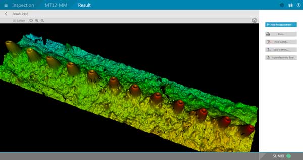
image from SUMIX
showing protruding fibers in MPO connector
More Than “Single” Mode?
Q: We're now using SM fibre so it looks like we don't
need mandrels in the Ref Lead at the Light Source. The
info I have is that we need to make a couple of air coils 35mm
to 50mm in diameter. Why?
A: When you launch from
a pigtial laser source through a connector into a reference
cable, you do have several modes being propogated. It usually
takes 100m or so for the second or third order modes to
attenuate. So the coil causes them to be attenuated by the
stress enough to no longer be significant - it’s a mode filter
just like MM. If you do not do this, you will measure higher
loss in the fiber and at connections near the source. Since most
SM has traditionally been long distance, the effect was small or
ignorable, but with short links, it can be significant.
Followup Q: But how do we explain multiple modes in Single Mode
fibre?
A: When you get the core of the fiber down to ~5-6 times the
wavelength of the light, it no longer acts like geometric optics
(like MM fiber). Some of the light can travel outside the core
(see the note on “waveguide
dispersion”here http://www.thefoa.org/tech/ref/testing/test/CD_PMD.html).
At launch, significant amounts of power are at higher angles
creating short lived modes that are highly attenuated.
Replacing OM1 MM Fiber
Q: We are an automation system integrator in South
Africa. We have a client that has multimode 62.5/125 fibre optic
plant wide. None of the runs between components are longer than
2km. We intend to upgrade the technology from a proprietary
communication protocol to a standard ethernet protocol at 100
MHZ. The fibre to copper convertors we will be using are using
1300nm light source and have a Fibre Optic Link Budget of 12.8dB
for 62.5/125 um and 9.8dB for 50/125 um. The
client has been advised to replace the multimode 62.5/125 with
multimode 50/125 cabling and we need to know if this is really a
requirement.
A: Do you know how old
the fiber is? It should be what we called FDDI grade 62.5/125
fiber with a loss of ~1dB/km and a bandwidth of 500MHz-km
at 1300nm. A 2km link should have a loss of 2dB for the fiber
and ~0.5dB/connection - well under the power budget of the link.
100Mb/s Ethernet variants were designed for 2km or more on this
fiber. There is no reason to upgrade at this time, 50/125 fiber
would not be needed until Gigabit Ethernet was desired.
Bi-Directional OTDR Testing
Q: Should the testing be done with the same piece
of equipment from both ends then merge the results or does that
not matter - can you use traces from two OTDRs as long as the
test equipment is compatible and settings are adjusted properly.
A: Yes, you should use
the same test set from each end but this way - take a trace,
disconnect the OTDR from the launch cable and go to the far end
of the receive cable and connect it there to take the second
trace. The usual way people do bi-directional tests is to
disconnect the launch cable and take it to the far end and shoot
back up, often not using a receive cable at all, figuring they
get the far end connector on the second test. But when you
disconnect the launch cable (and/or the receive cable) you lose
the connection you want to test in the other direction! As for
using the same OTDR, every OTDR is different and the results you
get may be significantly different, esp. if they are not
calibrated recently - and few OTDRs are ever calibrated.
Passive
OLANs in Hotels And Resorts
Q: Are passive OLANs a good choice for hotels or
resorts?
A: Passive Optical LANs
are enterprise networks based on fiber to the home (FTTH)
technology not Ethernet over structured cabling. The FTTH
network is usually using GPON standard equipment over one
singlemode fiber with passive optical splitters that provides
basic Level 1 and 2 network functionality. This is not Ethernet
but carries Ethernet over the GPON protocols at 2.5G downstream
and 1.25G upstream.
Passive OLANs offer several advantages over conventional
Ethernet switches and structured cabling, including much less
cost (~50% capital expense and ~20% operating expense),
much lower space requirements (see the link to the library
photos below and note the two racks of equipment that support
4000 drops), longer distance requirements (to 20km), easy
expansion (these are systems designed for hundreds of thousands
of users) and easy management (when you have hundreds of
thousands of users, that’s important.)
For hotels, convention centers and similar facilities, the ease
of upgrading to a passive OLAN is a big advantage - one fiber
goes from the computer room to a splitter where it can serve 32
switches of 4 ports each. That’s right, one fiber can support
128 users! It can support anything that a network can - wireless
access points, security cameras, secure entry systems, VoIP
phones or POTS phones - anything that will run over a
conventional network.
Calibrating
An OLTS
Q: I have a question about the OLTS - do you have to
recalibrate it every day ?
A: Any optical loss
test set needs to be calibrated for “0dB” whenever anything
changes - the launch cable - source output - or even every few
tests to ensure the connector is clean and undamaged - plus they
wear out. See 5
different Ways To Test Fiber Optic Cables.
Insertion
Loss
Q: I have not been able to find a good definition of
“optical insertion loss” or “insertion loss” or “optical loss.”
A: Insertion loss was
the term originally used for the loss of a connector tested by a
manufacturer. They would set up a source and length of fiber
connected to a meter, measure power, insert a pair of connectors
and measure the loss. Since it was an inserted connection, it
became known as insertion loss.
Over time, the term insertion loss became more widely used to
contrast with the loss measured by the OTDR, an indirect
measurement using backscatter that may not agree with the loss
with a light source and power meter.
Insertion loss, therefore migrated to meaning a loss measured of
a cable or cable plant inserted between the launch and receive
cables attached to a light source and power meter for double
ended testing used with installed cable plants. For patch cord
testing, you do not use a receive cable attached to the power
meter but connect it directly to the cable under test, making
the test just include the one connection to the launch cable.
Two other terms often mixed up are attenuation and loss, which
are essentially the same, except when discussing a fiber. In
fibers, attenuation is often used instead of attenuation
coefficient. Attenuation is the absolute loss i dB while
attenuation coefficient is the characteristic attenuation of a
fiber expressed in dB/km.
Here is probably the best explanations: http://www.thefoa.org/tech/ref/basic/test.html
Old
Fiber
Q: We are looking at a company’s fiber network which
has been laid at various points in time over numerous
years. In this process, we are trying to identify the
changes that were made to either/both the glass fiber and the
cladding. Are there different generations of what was
industry standard in creating the fiber? For example, are
you able to identify the difference in a fiber that was laid in
1980 versus one laid today? Was the cladding the same
size/thickness etc. in 1980 as it is today or has this been
modified/improved upon over the years? In all, we are
trying to find what modifications have been over the years and
how this may improve the life of the network and its
capabilities.
A: This is a common
problem today. Many network operators are evaluating their fiber
networks for upgrades, hampered by the fact that few are
properly documented. Below is a timeline that should answer your
questions. What many network owners are doing now is testing
their cable plants - a process called Fiber
Characterization. There are contractors who do this
service.
Fiber
Tech Timeline
1976 -
First field trials, US and UK, using multimode fiber at 850nm
1980 -
First long distance networks still using multimode fiber at
850nm, planning to upgrade with wavelength-division
multiplexing at 1310nm
1984 -
singlemode fiber becomes feasible, telecom drops multimode
fiber, all future installations are singlemode - this first SM
fiber with a 9 micron core and 125 micron cladding is still
available today but with better specifications. Really early
fiber may not have good environmental protection and degrades
over time. Early speeds were 145-405Mb/s, up to 810Mb/s by the
end of the decade.
1990 -
around this time, modern fiber begins - better performance and
environmental protection. Fibers for wavelength-division
multiplexing in the 1500nm range appear allowing multiple
signals on a single fiber and fiber amplifiers allow long
spans.
1995-2000
- massive build-out of fiber backbone leads to glut of fiber -
WSJ ~2001 says 93% of all fiber is dark. Speeds grew from
1.2-10Gb/s over the 90s decade
2000-date
- massive Internet growth and mobile device growth eats up
glut of fiber and demands many times more. Dense
wavelength-division multiplexing becomes the norm. Speeds
began at 1.2/2.5Gb/s, upped to 10, 40 and are now at 100Gb/s.
So most fiber installed after 1990 has the possibility of being
used at 10Gb/s, after 2000, it’s probably OK for 40Gb, and since
2010, you are probably OK for 100G and maybe more. To
verify performance, you test each fiber for connector condition,
loss, spectral attenuation, chromatic dispersion and
polarization mode dispersion. There are test sets that will do Fiber
Characterization in basically one step.
Fusion Splicing Live Fibers
Q: Is it safe to fusion splice a live fiber, or is
there a chance that
the light from the arc will damage the detectors in the modules
at the end (20km-rated SM for us).
A: I have never heard of
this being a problem. The amount of light coupled into the fiber
from the splicing would be very small compared to a properly
coupled laser. When a cable is broken you might be splicing the
fibers that are live without knowing which are live and not
caring. On your newer splicers this is not a problem. On the
older splicers with the LID system you would have to reduce the
power to get a good splice which they would do by putting a bend
in the Fiber.
Duplex
Communications Over One Fiber
Q: Is true duplex over a single fiber possible, or is
more like a shared time-domain technique in a quasi-duplex mode?
I would guess that true duplex would lead to interference
problems.
A. Bidirectional links
are widely used - that’s how FTTH PONs work. They use splitters
to combine/split the signals and one wavelength downstream and
another upstream. See Fiber
Optic Datalinks and for FTTH FTTH
Architectures.
Using
Hybrid 2.5-1.25mm Connector Mating Adapters
Q. Can I use the hybrid 2.5-1.25mm adapters for
connecting SC connectors to LCs or MU connectors. It would make
testing much more convenient.
A: We do not recommend
them for most uses, especially testing, as they can be highly
unreliable. Reserve them for emergencies and use hybrid patch
cords instead.
Test MM Fiber @ 1300nm?
Q:
What is your opinion about the need for testing at 1300
nm on OM3 and OM4 fiber especially now that bend insensitive
multimode fiber is taking over?
A: It’s
unnecessary and costly. It’s rooted in the FDDI/100M days 25
years ago when 1300 LEDs were used and is now obsolete. The
only actual uses at 1300nm I know are the extremely rare
systems using 1310 lasers which may be standards but simply
don’t seem to ever be used. As you say, BI fiber makes the
issue of finding stresses moot.
Fiber In Service Loops
Q: We designing a rural utility system that will be
expanded to FTTH (or FTTR - fiber to the ranch in this case).
We're wondering how much excess fiber in service loops to add.
One software package is asking for 12% but that seems excess.
A: I
have typically seen 100 feet on straight through boxes
(reserves), 35-50 feet on cut ends for splicing and anywhere
from 15-25 feet at the premise depending on how much is
required for the termination device, positioning, etc. When
rough estimating we have typically used 10% over linear
distance.
Maintenance of Fiber Networks
Q: Can you guide me how to prepare Optical Fiber
Cable Annual Maintenance Proposal?
A: Basically, the
network needs to be installed properly, fully tested and
everything carefully documented. Then no routine maintenance
is required. Most problems with fiber optic networks occurs
when techs are working with it, e.g. damaging cables or
getting connectors dirty when testing, so leaving it alone is
the best plan.
Electronic transmission equipment can be tested anytime to
ensure proper data transmission, but that does not involve
accessing the fiber.
We have several things which may be of help:
You Tube Video: FOA
Lecture 39 Maintaining Fiber Optic Networks
Web page: Maintenance
I have 4 questions about OTDRs:
Q: What is dynamic range I read many time but
can’t understand yet, whether it is a range of losses can be
measured by OTDR for example if an OTDR has 45 dB dynamic range,
it can read the losses of point up to 45 dB or what it means.
A: I do not believe there is a standard definition of
dynamic range, but it is generally accepted to be the highest
loss of the longest cable where you can see the end of the
cable. That usually means using the longest test pulse and most
averaging and assuming the end of the cable has a
significant reflection.
Q: What is dead zone is it fixed in meters mean an
OTDR cannot measure up to initial 5, 10 or 20 meter
A: The dead zone is a function of the pulse width and
speed of the OTDR amplifier. For most OTDRs it’s about 2-3 times
the test pulse width.
Q: What Type of settings needed before launching a
test
A: See FOA
Lecture 18: OTDR Setup or the section "Modifying OTDR
Setup Parameters For Best Test Results” in
OTDR
testing. A: Basically you set up wavelength(s), test pulse
width (long enough to reach end of cable but short enough for
best resolution), index of refraction or group velocity (a
function of the fiber type and wavelength) and the number of
averages (enough to mitigate noise but not take too long)
Q: Reading a test with 1310nm and 1550nm - why values
different for a same length of fiber.
A: The attenuation of the fiber will be different at
each wavelength and the index of refraction which is different
at each wavelength causes a difference in length. The OTDR
measures length by measuring time and then multiplying that by
the speed of light in the fiber (which is the inverse of the
index of refraction.)
The FOA page "Frequently
Asked Questions About OTDRs" answers these
questions and more.
Getting
Old Cables Out Of Conduit
Q: How do you get old cables out of a conduit when
they are stuck?
A: Usually we are concerned about reducing friction
when pulling cables through conduit, but sometimes you need to
get them out. Here
is a page from American Polywater the leading lubricant
company with advice on the subject.
Manufacturing
Guide?
Q: Is there a guide published by FOA that provides
insight as to the process of fiber optic manufacturing? It's my
understanding that the guide stresses quality and controls to
ensure performance and reduce product loss?
A: We do have a guide
for manufacturers. It is mostly aimed at communications systems
and components manufacture. Here
is a link to download it.
How
Long Does Termination Take?
FOA received a request from a consultant recently wondering if
we had information on the termination times for fiber optic
cables. After some looking in our archives, we realized we had a
document online that compared times for various fiber optic
termination processes. The paper was written after several FOA
instructors did a comprehensive time and motion study on
termination processes. The document is about 15 years old but
still relevant.
You
can read it here in the FOA Online Guide.
Testing
Connectors (From A Patchcord Maker)
Q: What are the chief defining standard(s) that
specifies connector and assembly IL (insertion loss) and RL
(return loss or reflectance) for both SM and MM fiber?
A: The description on
our Guide is here: http://www.thefoa.org/tech/ref/testing/test/conntest.html
FOTP-34 covers connector testing as a qualification test
for the type of connector - basically a "destructive" test for
connector manufacturers.
Reflectance is described on that page and here also: http://www.thefoa.org/tech/ref/testing/test/reflectance.html
Testing an assembly like a patchcord is covered under
FOTP-107 http://www.thefoa.org/tech/ref/testing/test/FOTP-171.html
Basic
Tests For Fiber Optic Cable Plants
Q: I did some research and I noticed that there is a
bunch of tests that can be done to fiber optics and I was
wondering if there is a list of primary tests that can be done
as a basic test.
A: Fiber optic testing
does have a hierarchy of tests.
- At
the top of the list is "insertion loss" testing which uses a
light source and power meter to test the fibers in the
same way that a communications system transmits over the
fiber. It is a simple test and the equipment needed is
inexpensive.
- Techs
will also use a microscope to inspect the fiber optic
connectors for dirt and damage, a big issue for fiber.
- The
instrument called an "OTDR" takes a snapshot of the fiber
using a technique like radar. Most outside plant cables are
tested with an OTDR and the data ( the snapshots are called
"traces") stored for future reference. OTDRs are more
expensive and require more training to use properly.
Here is a
link to a page on the FOA Guide site that explains the
technical,details: http://thefoa.org/tech/ref/testing/test/OFSTP-14.html
FOA also has information just for users of fiber optic networks,
see http://thefoa.org/tech/guides/UG3.pdf
How
to Clean POF (plastic optical fiber)
Q: I
heard that plastic fibres such as PMMA can suffer damage from
cleaning from an alcohol solution. Are there alternate cleaning
solutions available for these types of fibres."
A: You can use a 10/90
mix of isopropyl alcohol/water. Typically use with a lint
free swab. (from out POF consultants)
Testing
Bare Fibers With OTDR
Q: We are starting to test some OPGW cables. We have an
OTDR but we don’t find some reusable connectors. If we have to
test an OPGW with 48 fibres, we can’t set up 48 SC connectors!
Are there some reusable connectors in the commerce?
A: I assume you mean you
need to test with a bare fiber on the OPGW. For testing bare
fiber, use a splice, not a connector. Have a long pigtail on the
OTDR as a launch cable, long enough for the test pulse to
settle, say 100-500m, then use a splice for a temporary
connection. You can fusion splice the fibers then cut the splice
out or use a removable splice like the Corning Camsplice
(http://catalog.corning.com/opcomm/en-US/catalog/ProductDetails.aspx?cid=&pid=17929&vid=18219)
If you use a mechanical splice, you need a high quality cleaver
just like with fusion splicing and after several uses, you need
to add more index matching gel or liquid - mineral oil works OK.
See
the FOA page on Testing
Bare Fiber.
Is A Flashlight Test Adequate?
Q:
I contracted a firm to install an OM3 of 200 meters. On
one end I have an SFP 1000SX ,on the other a 1000SX
converter from optical to UTP. We made pings but they never
reached, and I didn’t see the laser at the extreme of the fiber.
They promised me to send me the certification they supposely
made ,though they assured me the fiber is ok, because WITH
A FLASHLIGHT THEY SENT WHITE LIGHT FROM ONE SIDE TO THE OTHER
AND IT WAS VISIBLE. I saw the light too, and I thought the
culprit was my switch or my SFP. I want to know: is this a good
demonstration that the fiber is ok?
A: A visual continuity
test is not adequate - your eye is not calibrated! The power of
the lamp is unimportant as each eye’s sensitivity is different.
And your eye probably cannot see the light from a 850nm VCSEL
source - most people’s eyes are not sensitive at that infrared
wavelength. The installer should have tested the link with a
light source and power meter (http://www.thefoa.org/tech/ref/testing/test/OFSTP-14.html)
and given you the loss in dB. The connectors should also be
inspected with a microscope to ensure proper polishing and
cleanliness
(http://www.thefoa.org/tech/ref/testing/test/scope.html). If the
SFP output is -6dBm, what is the power at the receiver?
1000base-SX is supposed to work with 4.5dB loss (see
http://www.thefoa.org/tech/Linkspec.htm). The fiber loss should
be ~0.6 dB, so you must have >4dB connector losses! That says
bad installation! The 1000SX link should work over 200m if the
fiber has been properly installed.
Older Fiber?
Q: I have some 62.5 mm and sm inside fiber plant over
20 years old. When is a good time to upgrade?
A: When you need to or
have to. If it's working OK, there is no need to upgrade!
"Connector Loss" or "Connection
Loss"
Q: I have always counted the loss of a connector as .75
dB (568B-3) and 1.5 for a mated pair. Is that correct?
A: While the industry
always says "connector" loss, it is actually "connection" loss.
As we explain in the page on termination and splicing (http://www.thefoa.org/tech/ref/basic/term.html)
When we say "connector" loss, we really mean "connection" loss -
the loss of a mated pair of connectors, expressed in "dB." Thus,
testing connectors requires mating them to reference connectors
which must be high quality connectors themselves to not
adversely affect the measured loss when mated to an unknown
connector. This is an important point often not fully
explained. In order to measure the loss of the connectors
you must mate them to a similar, known good, connector. When a
connector being tested is mated to several different connectors,
it may have different losses, because those losses are dependent
on the reference connector it is mated to."
The
TIA spec of 0.75dB is for a mated pair of connectors. If you
have been passing connectors tested @ 1.5dB loss....you may have
some very bad connectors in your cabling!
Microscope
Magnification (11/13)
Q: I am doing a lot of fiber optic jumpers for control
systems, either single mode or multimode. I want to get a
scope to inspect the ends after I clean them would you recommend
a 200X, 400X handheld or one similar to a Noyes OFS 300
200C?
A: We prefer to use
lower magnification and have a wider view so I can see more of
the ferrule to determine its condition. You can see the fiber
effectively at 100X but 200X may be better. 400X may be too much
for most tasks like inspecting for cleanliness, but may be good
if you are polishing SM for good reflectance. We've used the
Westover units for years because they offer two different
methods of illumination - direct and at an angle. If you are
doing a lot of patchcords, I recommend a video microscope. I've
used the Noyes unit that interfaces to a PC to create the FOA
Microscope Inspection YouTube video here: http://www.youtube.com/watch?v=IyumH8CiUPQ&feature=youtu.be
and it works well.
Recycling Cabling
Q: Who can I contact regarding recycling cable I am
removing from a building?
A: Here are some people
who say they recycle fiber optic cable or at least know how to
do it:
http://www.scottrecycling.com/complete.html
http://www.scrapmonster.com/selloffer/fiber-optic-cable/10400
http://www.dnvkema.com/services/ces/hse/recycling/recycling-cables.aspx
http://tmscrapmetals.com/Recycling.html
Tech
Hint: Did You Know You Have A Fiber Optic Tester In Your
Pocket?
Yes!
That old mobile phone has a camera which may be sensitive to
infrared light - lots more than your eye - and can detect
light in an optical fiber or from a transmitter. Chris
Hillyer,CFOT/CFOS/I, Master Instructor, Northern California
Sound & Communication JATC sent us some photos showing how
this works. See below
or the video
now on YouTube. Update: You should check out your old
cell phones before you recycle them. We've found older models
use sensors which are better at infrared than the newer ones
which take better pictures. This is a good use for your old
cell phones hiding in the drawer!
Fiber
Cleaning
This is a topic we keep reminding everybody about, and here is
why:
From
a contrator in the Middle East: Here some samples of the
connectors for SM fiber already installed in the system we were
testing.
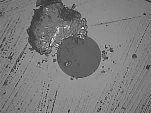
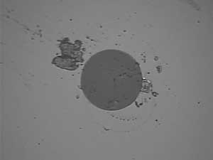
As
you can see, the dirt is large compared to the size of the fiber
(dark gray), and the core (not visible here) is only 9/125 of
the overall diameter of the fiber!
Clean
Every Connector - A Lesson We Learned From Creating Lessons
In creating
the fiber
characterization
curriculum, we got inputs from many experienced techs about the
testing requirements. Everyone we talked to made a big point
about cleaning and inspecting connectors before testing. Dirty
connectors are a major problem with errors in testing. We've
also seen that many installers think that if a connector,
especially new connectors, has a "dust cap" on the connector, it
does not need cleaning. WRONG!
The common name for the plastic caps on connector ferrules is
"dust cap" and a friend says they
are called "dust caps" because they are full of dust.
Those plastic caps are made by the millions, popped out of
plastic molding machines into barrels and stored until put into
plastic bags. Whenever you remove one of them, clean the
connector before testing or connecting it.
More on connector cleaning is here and here.
More
on cleaning. See Product
News below for links to vendors of fiber cleaning products.
What
You Need To Know About Fiber Optic Cleaning And More
Ed
Forrest, one of the industry experts on cleaning fiber optic
connectors, retired about a year ago. We encouraged him to put
down on paper what he knew about fiber cleaning and he took our
advice. He's now created 4 books on cleaning topics that cover
just about everything you need to know. And he added another
volume that's also important - maintaining fusion splicers. We
recommend these books highly.
How to Precision Clean All
Fiber Optic Connections
Understanding Cross-Contamination Points on Fiber Optic
Inspection & Test Equipment
Maintaining a Fiber Optic Fusion Splicer
Comparison Study of Precision Cleaning Methods for All Fiber
Optic Connection
Whitepaper: The Significance to Optical Internconnect:
Properly Cleaning a Fiber Optic Connection
Information on Ed's books is at http://fiberopticprecisioncleaning.com/available-books-whitepapers/.
See
news about Fiber Optic Cleaning Videos on YouTube by ITW
Chemtronics below.
Fiber Optic Cleaning Videos on YouTube
See news about Fiber Optic Cleaning Videos on YouTube by ITW
Chemtronics three fiber optic cleaning videos on YouTUbe
covering Dry
Cleaning, Wet-Dry
Method, FiberWash
and Combination
Cleaning. They are good explanations of cleaning processes
- the Wet-Dry is especially interesting.
Measurement
Uncertainty: Everyone testing fiber optics should understand
that every measurement has some uncertainty - whether you are
measuring loss, length, wavelength, power, etc. Knowing that
uncertainty is very important to interpreting the measurement.
It's worthwhile to read and understand the issue of measurement
accuracy covered in this
page of the FOA Online Fiber Optic Reference Guide.
RETURN
TO INDEX
Worth
Reading or Watching:
Sign
up at the FOA Pinterest
board 
FOA
"Quickstart Guides"
In our
continuing quest to help people understand how to test fiber
optic cable plants and communications systems, we've created two
more "QuickStart Guides to Fiber Optic Testing." They are
simple, step-by-step guides on how to test fiber optic cable
plants, patchcords or single cables using insertion loss or OTDR
techniques and optical power from transceivers. It's as
straightforward as it can get - what equipment do you need, what
are the procedures for testing, options in implementing the
test, measurement errors and documenting the results.
It can't get much simpler.
Send anybody you know who needs to know about fiber optic
testing here to learn how it's done in a few minutes.
Testing
Fiber Optic Cable Plants And Patchcords
Testing
Fiber Optic Cable Plants With An OTDR
Measuring
Optical Power In Communications Systems
Like
Crossword Puzzles? Here's Some On Fiber Optics
Do you like
crossword puzzles? How about one on fiber optics - or maybe a
half-dozen of them? FOA Master Instructor Eric Pearson of Pearson
Technologies has created a series of crossword puzzles on
fiber optics that are keyed to the FOA CFOT reference materials
and his book Professional
Fiber Optic Installation, v.9. You can have fun and
study fiber optics at the same time!
This months crossword puzzle is on "Optoelectronics and
Splicing" - Download
the crossword puzzle on "Optoelectronics
and Splicing."
If you
missed the earlier puzzles, here they are:
Download
the PDF file of the crossword on "Light and Fiber".
Download
the PDF file of the crossword puzzle on "Cables".
Download
the crossword on "Connectors
& Splices."
Older
Fiber, Do You Know How Good It Is?
There's
millions of miles of long distance fiber installed around the
world and most of it likely to see an upgrade of the systems
operating on it, probably in the near future. Twenty years ago,
most of it was probably running at ~1Gb/s, ten years ago it was
probably 2.5 Gb/s, recently it was likely to be 10Gb/s but now
many are being considered for 100Gb/s or beyond. Can the fiber
support such speeds? Can it be "repaired" or "modified" to make
it possible to use it at higher speeds? If you own that fiber,
can you say what it is worth without knowing its future upgrade
capability.
In order to know the potential for upgrades on your cable plant,
you need to test it. This process involves a number of tests and
is called "fiber characterization." Greg Stearns of TTP-US, an
FOA Corporate Member, performs these tests and has written a
short article on why you need to characterize fiber and how its
done. Read about fiber characterization from someone who does it
often and can explain it well.
Download
the paper here (PDF, 80kB).
Demystifying
Singlemode Fiber Types
Singlemode
fiber has a lot of names and users are confused by the different
names depending on the standards organization you refer to IEC,
ITU or TIA designation. Most widely used are the ITU G65X
designations but even there we find many designations. Shaun
Trezise of M2FX has posted a simple explanation on the company
blog that helps explain the different types and where they are
used. Read
more on the M2FX blog
There is a cross
reference to the IEC, ITU and TIA designations on the FOA
Guide.
EXFO
Offers Super Posters And More

EXFO offers some super posters, guides and books. The FTTx and
OTDR posters are really useful! Look
at the whole selection here.
Getting Cables Out Of Conduit
Usually we are concerned about reducing friction when pulling
cables through conduit, but sometimes you need to get them out.
Here
is a page from American Polywater the leading lubricant
company with advice on the subject.
What Is The FOA?
Hear FOA President Jim Hayes tell the FOA Story in a 2-part
interview by Sound & Video Contractor Contributing Editor
Bennett Liles. It tells about the FOA history, goals and
achievements.
Part 1: http://svconline.com/podcasts/audio/fiber_optic_association_part1/index.html.
Part 2 http://svconline.com/podcasts/audio/inside-fiber-optic-association2-0924/index.html.
What
Happens To Old Fibers?
In a recent web search, we found this article from Corning,
reprinted from a IWCS presentation in 1995. It discusses
extensive tests on a 1984 cable installed in the northern US to
see how it had degraded in almost 10 years. It is interesting to
see how the fiber survived OSP exposure. Read
it here.
Australia's
Standard Is Comprehensive Guide To Customer Cabling (Get your
copy free)
In
answering a recent technical questino, Trevor Conquest in
Australia pointed to the Australian Standard "Installation
Requirements For Customer Cabling." When we checked, it is on
the web and can be downloaded. It's a big book - 220 pages -
full of details for fiber and copper installations. We recommend
you download
yourself a copy - go here.
Demystify
fiber inspection probe technical specifications -
From EXFO
The
intent of this application note is to promote a better
understanding of video inspection probe specifications and
features. Properly understanding the key specifications
and features will greatly facilitate the decision process
involved in acquiring such devices. Understanding the key
aspects of fiber inspection probes will also help users
understand how fiber inspection probes operate, thus
enabling them to maximize the full potential of these
devices. Read
more.
Where
In The US Do Contractors Need Licenses For Fiber Optics?
We often
get asked where in the US do contractors doing fiber optic
installations need licenses. We found a good website for that
information, the NECA -NEIS website. You might remember
NECA-EIS, as they are the partner with the FOA in the NECA/FOA
301 Fiber Optic Installation Standard. NECA is the National
Electrical Contractors Association and NEIS stands for National
Electrical Installation Standards. They have a very easy to use
map and table that gives you data on every state in the US, so
mark these pages for future reference.
NECA/NEIS
http://www.neca-neis.org
(See “State Regulations”)
http://www.neca-neis.org/state/index.cfm?fa=state_regs
(all electrical licensing)
Low Voltage: http://www.neca-neis.org/state/index.cfm?fa=specialty_licensing
How Is
Fiber Manufactured?
OFS invites you on a tour of their multimode fiber manufacturing
facilities in this new 5-minute video. You will see their highly
automated manufacturing operation in Sturbridge, Mass.,
including their patented MCVD preform fabrication process to
fiber draw and final product testing. With a technological
heritage dating back to AT&T and Bell Labs, OFS has been
manufacturing high-quality multimode fiber since 1981.
Watch
the video here.
Benchmarking
Fusion Splicing And Selecting Singlemode Fiber
We've been asked many times "How long does it take to splice a
cable?" It's not a simple answer as it varies with the number of
fibers in the cable and the work setup, including whether one or
two techs are working at a job site. FOA Master Instructor Joe
Botha of Triple Play in South Africa did his own analysis based
on decades of experience both splicing cables and teaching
others how to do it properly. This is one of the best analyses
we have seen because Joe includes prep times as well as splicing
times and differentiates between one tech and two techs working
together. He adds some other tips on fusion splicing too. This
should be mandatory reading for every tech and given to every
student! Here
is Joe's splicing analysis.
Joe also has an excellent writeup on how
to choose singlemode fiber that helps understanding
the different types of G.6xx fiber. Read
it here.
And you will want to read Joe's report on splicing
different types of SM fiber, including bend-insensitive
(G.657) fiber. Read
it here.
Free
- Mike Holt's Explanation Of The US National Electrical Code
(NEC) For Communications Cables
Mike Holt
is the acknowledged expert of the US National Electrical Code
(NEC). His books and seminars are highly praised for their
ability to make a very complicated standard (that is in fact
Code - law - in most areas of the US) easily understood. Part of
the appeal is Mike's great drawings that make understanding so
much easier. Mike makes Chapter 8 of his book available free. It
covers communications cables, telephones, LANs, CATV and CCTV,
for premises applications. Even if you live in a region or
country where the NEC is not the law, you may find this
interesting.
Download
Mike's Chapter Here.
Fiber
Optic Cleaning Videos on YouTube
ITW
Chemtronics has three fiber optic cleaning videos on  covering Dry
Cleaning, Wet-Dry
Method, FiberWash
and Combination
Cleaning. They are good explanations of cleaning processes
- the Wet-Dry is especially interesting.
-
- Download
yourself a copy and read it!
-
Good
Technical Website For Installers
American
Polywater (http://www.polywater.com/)
has one of the best technical website for cable installers. Check
out their website, especially “Videos,” “Engineer’s Corner”
and “Calculators.” http://www.polywater.com/NNNBSL.pdf
Fiber
Optic Safety Poster
We've had numerous requests to reprint our guidelines
on safety when working with fiber optics, so we have
created a "Safety Poster" for you to print and post in your
classroom, worksite, etc. We suggest giving a copy to every
student and installer.
RETURN
TO INDEX
-
FOA
Tech Topics -
A
Fiber Optic Tester In Your Pocket? (See the video on
 )
)
Yes!
The camera in your old cell phone is sensitive to infrared light
- lots more than your eye - and can detect light in an optical
fiber or from a transmitter. Chris Hillyer,CFOT/CFOS/I,
Master Instructor, Northern California Sound & Communication
JATC brought this to our attention.
If
you have an old cell phone, try it. Our experience is that older
cell phone cameras have better sensitivity at IR wavelengths
than newer phones, so you may want to toss that old flip phone
into the toolbox.
RETURN
TO INDEX
Product
News
New
Ripley Fiber Stripper
Ripley
recently sent us some new fiber strippers to try, the Ripley
Tri-hole fiber stripper model CFS-3. It is aimed at
contractors and installers and is very reasonable prived - plus
we understand there are some introductory price specials from
some distributors.
The CFS-3 can strip fiber jackets, 900 micron buffer and 250
micron buffer for one step cable preparation.
- 1st hole strips 1.6 – 3mm Fiber Jacket to the 600-900 buffer
coating.
- 2nd hole strips the 600-900 micron buffer coating to the 250
micron coating.
- 3rd hole strips the 250 micron buffer coating to the 125
micron glass fiber.
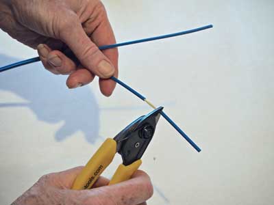
We tested
the CFS-3 on several fibers and cables and found it easy to use
and very consistent. It seemed much less sensitive to the angle
you hold it at when stripping fibers than some strippers like
this and it was very effective even stripping some older, more
brittle fibers.
Here's
more information on the Ripley CFS-3 Part #: 81300.
VIAVI
Introduces OLTS For MPO Connectors
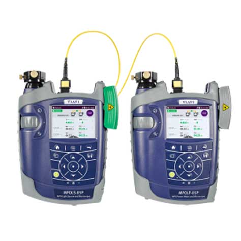
One of the biggest problems with multifiber MPO connectors is
testing. Viavi Solutions (formerly JDSU) has introduced its
SmartClass Fiber MPOLx optical loss test set, a basic test
solution for cabling systems that utilize multi-fiber MPO
connectors. The testing of parallel optics with MPO connectors
has always been difficult for regular single or dual fiber OLTS,
needing MPO to SC or LC breakout cables for testing one fiber at
a time and using the three cable “0 dB” reference method. The
MPOLx should make testing cable plants using these connectors
much easier.
The MPOLx can test for length, optical loss, polarity and
inspect fiber end-face condition - a complete cable plant test.
The ability to check polarity is important since there are
several polarity schemes used in MPO systems. The MPOLx is fast
too, delivering comprehensive test results in less than 6
seconds for all 12 fibers.
More
information on the Viavi MPOLx here.
YOKOGAWA OTDR Has Extended range, High Resolution And Multitasking
One OTDR manufacturer you don't hear as much about is YOKOGAWA
(formerly ANDO) which is too bad - they make some of the best
OTDRs, exemplified by this new model AQ7280. Need long range -
how about 50dB. High resolution - 0.6m dead zone. Like touch
screens, but for some functions want hard buttons, it's got
that. Options for VFL, microscope, light source and power meter,
etc. - it has that too.
But the unique aspect of the YOKOGAWA AQ7280 is it offers
multitasking - you can let do a trace with long averages while
you inspect connectors, make power readings, use the VFL or
other functions.
More
info on the YOKOGAWA AQ7280.
FOA
thanks Yokogawa for a gift of an OTDR to use for R&D and
teaching!
Recycling Communications Cable
FOA was
contacted by a company that recycles electronics communications
equipment and cabling. CommuniCom recycles
cable/metals/e-waste
for Telcos and CATVs. They also recycle Fiber Optic Cable and
associated Materials (the fiber scrap). And, they reclaim OSP
abandoned copper cables (abandoned from road moves or FTTx
growth). This is a huge part of our business. They do the work
(permitting/locates/labor) for free and we revenue share back
with our clients (telcos).
Contact
Steve Maginnis
smaginnis@communicominc.com
www.communicominc.com
803.371.5436 (cell)

Micro-Trenching, Cable
Removal
Nano-Trench
offers products for micro (or I guess they call it nano-)
trenching and their
website is very informative. They also have Kabel-X,
a method of extracting copper cables from old conduit. Both
websites are informative and interesting. Watch
this video on the cable removal process!
Protecting Pedestals From
Rodents
Pedestals
and underground vaults can be damaged by rodents who come up
through the base and damage cables. Uraseal "Drain N'Seal"
foam deters mice from taking up residence in your pedestals. They
have some good videos on using their product.
Used
Test Equipment – Buy or Sell
http://www.testequipmentconnection.com/
Have
you read the FOA
pages on cleaning?
- RETURN
TO INDEX
FTTH
Notes:
- Want
To Learn More About FTTx? Try our free online self-study
program at Fiber
U.
|




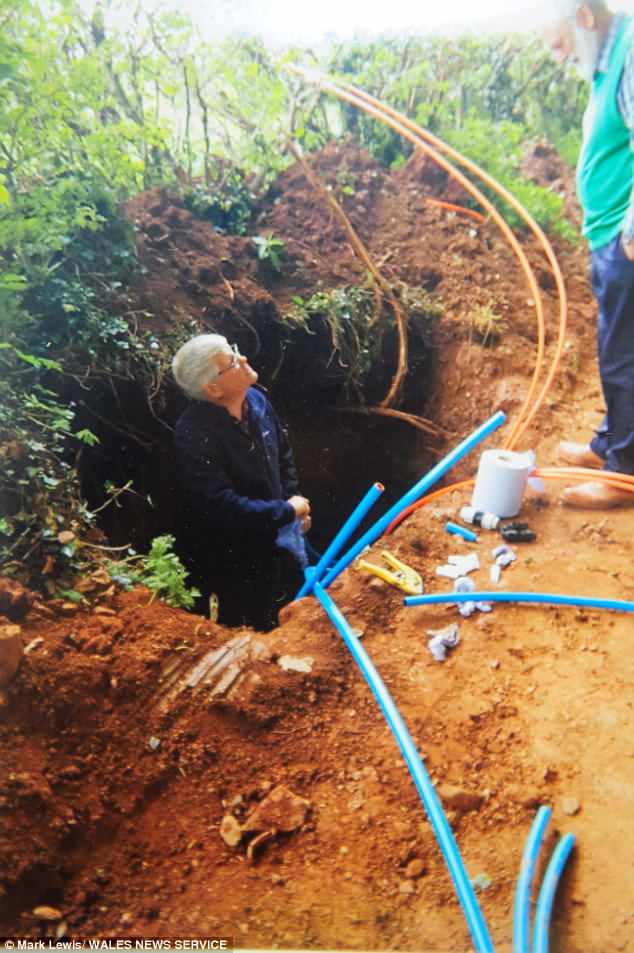
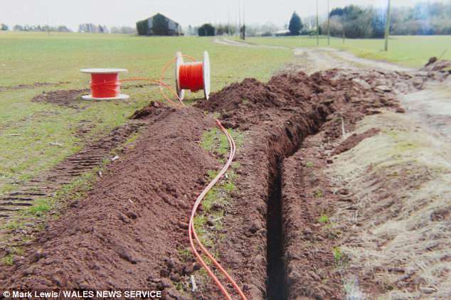
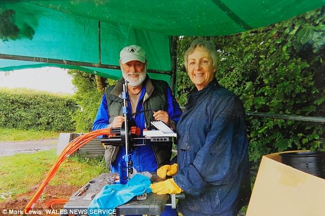




 FirstNet photo


 Morse and his telegraph


 Superior Essex Comparison Of Cable Efficiency


