Fiber
Optic Cable Plant - Acceptance Of The Finished Product
- Deliverables
What
is involved in the specification and acceptance of a cable
plant at the end of a installation project and what are
reasonable specifications for a cable plant. FOA has a lot
of documentation on a project involving designing
and installing a cable plant in the FOA Online Guide and
our Textbooks, but the acceptance process is relegated to
a few paragraphs. Let's look at a project and include a
few links to FOA tech documents in case you want to
investigate further.
The Project "Deliverables"
Fiber optic projects start with a design
that creates project
paperwork - the scope of work (SOW), request for
proposal or quote (RFP/Q) and a contract with the
builder/installer. A "Scope of Work" document is created
by the initiator of a project to describe the work to be
performed or the services to be provided by a contractor.
It describes tasks to be performed, directs methods to be
used, and defines the period of performance. It should
contain design and performance requirements. A scope of
work for communications cabling or fiber optics may be
part of a larger building project document that is based
on a standardized format called "MasterFormat"
in the US and Canada.
A well written scope of work can do more for the success
of a contract than any other part of the contracting
process. A good scope of work is clear, complete, and
logical enough to be understood by the respondent and the
personnel who will administer it. Because it describes the
details of performance, it is the yardstick against which
the respondent's performance is measured. That is why the
user's requester, contract administrator and/or subject
matter expert should be the focal point for developing the
scope of work.
What we are discussing here is the final product - the
"deliverables" - that define the final product that the
end user expects to have when the installation is complete
and ready to use, or in some cases already has the
communications equipment installed and operating. Of
course the deliverables include the physical cable plant
described in the SOW, but also must include full
documentation and test results, and maybe even a warranty.
Cable Plant Specifications
What are reasonable specifications for a cable plant.
We've often heard stories of specs that are too stringent
and others too lax. Since specifications for the installed
cable plant are up to the person specifying the cable
plant, they may be confusing because very few standards
exist for the design and specification of the cable plant.
OSP networks have traditionally been specified and owned
by sophisticated users who have a history of what specs
can be expected. Premises cabling systems tend to use
component specs from TIA or ISO/IEC standards that are
generally too lax, much higher than what should be
expected.
Let's do the executive summary. The cable plant should be
specified for loss using a loss budget. Network speed may
dictate specifications for component types or bandwidth.
Here is a summary of FOA's "reasonable specs" to use for
cable plant loss budgets. Below we'll get into testing
with loss budgets based on those specs.
OSP
Fiber: G.652 attenuation 0.4dB/km at 1310nm, 0.25dB/km @
1550nm
Splices: Average 0.1dB, reject @ 0.2dB
Connections: Average
loss 0.3dB, reject @ 0.5dB, Reflectance better than
-40dB.
Long haul fibers like G.654 will have slightly better
attenuation specs, ~0.2dB/km.
Premises
Fiber:
Multimode OM3/OM4 attenuation 3dB/km @ 850nm, Bend
insensitive fibers
Singlemode
OS1/OS2 attenuation
0.5dB/km @ 1310nm, Bend
insensitive fibers
Splices: Average 0.3dB, rare in premises
Connections: Average
loss 0.5dB, SM reflectance better than -40dB.
Cables types, of course, are specified according
to the requirements of the project and it's
physical locations.
Documentation
The final documentation delivered to the customer must be
comprehensive, with full route information including GIS
(geographic information system) data on the location of
the cable and every component - cables,
manholes/handholes, splice locations and full
descriptions, plus test data. The physical component and
location information is obvious, but what is not is test
data, which we elaborate on below.
What's sometimes missing, based on inquiries we get from
end users, is understandable documentation. Managers who
may not be familiar with fiber optics can be given reams
of documentation which they are expected to use to sign
off on a project. There are many stories about problems at
this stage: signing off on a data center installation
where all 4,000 connectors were failures, getting test
data on a OSP network where every OTDR test was the same,
you get the idea. Before signing off on a project, someone
who knows fiber optics and was involved in the project
should review the documentation and test data and verify
that it is correct and valid.
Cable Plant Test Data
To prove the cable plant was installed properly requires
test data, of course. During the design phase, loss
budgets calculated for each cable run should provide
an estimate of the expected loss of the fibers in each
cable link to compare to actual test results.
Short
fiber optic premises cabling networks are generally
tested in three ways, connector
inspection/cleaning with a microscope, insertion
loss testing with a light source and power meter or
optical loss test set, and polarity data, meaning that the
routing of fibers is confirmed so that when connecting
equipment the tech can identify fiber pairs for transmit
and receive. Polarity testing generally can be done with a
visual fault locator to confirm that fibers are connected
per the documented cable diagrams.
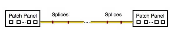
Outside plant (OSP) testing is more complex. If the cable
plant includes cables concatenated with splices, it's
expected to add OTDR
testing to the connector inspection, insertion loss
and polarity testing. If the link has passive devices like
FTTH splitters or WDMs, those need to be tested and
documented also.
There is one thing that whoever is reviewing the data -
and going back to the design phase, whoever writes the
test specifications based on the loss budgets in the first
place - needs to understand: none of these are
absolute numbers. The loss budget which is
created early in the design phase estimates
the loss of the cable plant based on estimates
of component loss and therefore is not an absolute number,
but an estimate to be used to compare to
test data.
Test data is created by instruments and related components
that make measurements which have measurement
errors. There are always factors in making
measurements that cause the instrument reading to be
inaccurate - only an approximation of the real value
- and the real value is unknowable because of measurement
errors. (If you are curious, look up the Heisenberg
uncertainty principle.)
Let's
look at this symbolically:
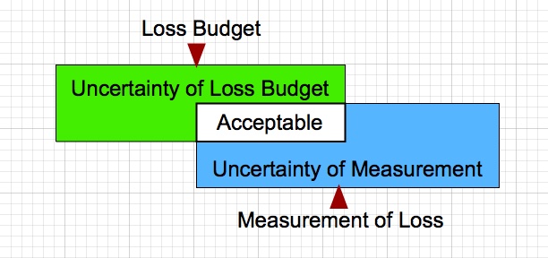
The loss budget is not exact, nor is the testing,
so there is a range of measurements that should be
acceptable. Some judgement is needed to determine
if a particular fiber's test results are
acceptable. In our
experience, those two factors cause more stress between
managers and installers than just about any other factor
in a cable
plant project. Consider these examples of the issues
with loss budgets and testing errors.
Examples
OSP Cable Plant
Here is the situation a CFOT found themselves in when
they called the FOA. They were an 30+ year experienced
splicer with a half-million splices of experience. A
customer wanted to specify a long cable plant (~50
miles/80km) with splices that averaged 0.05dB and any
splices above 0.15dB was not acceptable. Testing of the
splice loss would be done with an OTDR with
bidirectional measurements and averaged.
What
made this call particularly interesting is this tech had
some real world data, the kind you do not see often. On
a past job, he had spliced a ~60 mile (100km) 288 fiber
cable plant at 18 splice locations, that's 5,184
splices. His test records showed that 60% of the splices
were in the range of 0.02 to 0.08dB and 40% were in the
range of 0.08 to 0.15dB. Only 17 splices were over 0.15dB.
The
customer noted that the
manufacturer
of the splicer used by the tech quoted a splice loss
capability of 0.02dB, so a field spec of 2.5 times that
should be easily achievable in the field. What the
customer did not understand was that 0.02dB
spec for the splicer was data taken in a laboratory
on a new or perfectly set up machine. The splices
were made by breaking a fiber and splicing it back
together. Every splice used in determining the
splicer capability used identical fibers - they were
the same fiber.
In the field, when splicing cables together, the
environment is not like a lab. Machines are used to
splice thousands of fibers. The fibers in the cable
can be from numerous production runs and will have
variations in mode field diameter (MFD) and
geometry. Assuming a long haul network like this one
is using G.654 fiber, we can look at the ITU
standard for G.654 fibers and we find these
specifications:
Mode Field Diameter: 9.5-10.5microns
Core Concentricity Errors: 0.8micron
That variation in fiber geometry and MFD can produce
a real difference in splice loss that will be
directional. That difference can be 0.05 to 0.1dB.
That is independent of how well the splicer can
align and fuse fibers. Even if aligned perfectly
and spliced
perfectly the differences in the fiber will cause
directional splice differences - higher in one
direction, lower in the other.
The can be a 0.20 to 0.25dB difference in
directional splice loss when measured by an
OTDR
caused by MFD variation in the fibers
(data from Corning ap note AN3060). This is
something which many techs are familiar with, but
that method of bi-directional testing merely removes
the OTDR scattering error and gives the average of
loss from each direction. It can't compensate for
the actual directional splice loss caused by the
difference in MFD. Let's repeat that: Bi-directional
OTDR testing removes the OTDR error caused by
differences in fiber MFD or backscattering, but
cannot compensate for the actual directional
difference in splice loss caused by the difference
in MFD.
Back to the customer's spec. They wanted an average
splice loss of 0.05dB and no splices over 0.15dB -
which was unacceptable. Using some math, we can
analyze the data the tech had from the prior 60 mile
(100km) job. The average splice loss on that cable
plant was ~0.07dB. And only 17 were larger than
0.15dB, so the reject rate would have been 0.3%.
If we compare the results of that job to the specs
the customer wants on the new job, the difference
would be 0.02dB/splice at 18 splice points. The
total loss difference in the 60
mile (100km) cable plant would be 0.02dB X
18 or 0.36dB - and that is on a
60 mile (100km) run where the fiber
loss is 0.20dB/km X 100km or 20dB.
And the loss of the original 18
splices was only ~1.33dB! The
difference is negligible and the
measurement uncertainty of the OTDR
test of end-to-end loss is much
bigger than the difference.
Premises Network
In premises fiber optic networks, the TIA standards
allow for connections to have a loss of 0.75dB - that is
two connectors mated to create a connection. A
fiber optic connector has no loss, per se, because
it is not being used. When in use, it is mated to
another connector creating a joint between two
fibers, and that joint is what has loss - a
"connection" loss.
That number has been in the standards
for at least 30 years, but even then typical connectors
with ceramic ferrules were much better than that. That
0.75 dB loss was needed for early connectors like SMAs
and Biconics, so it became the standard, Later, although
everyone knew that the typical ST, SC, FC and then LC
connector was much better, the industry saw the
introduction of array connectors (MPOs) where the 0.75
dB loss was needed, so rather than have different values
for single fiber and array connectors, it was left at
0.75dB.
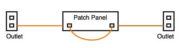
If you do a loss budget for a premises network with an
intermediate patch panel like the one above, your loss
budget would include 4 connection losses, the two in the
patch panel and the ones in the outlets at each end
where you connect the patchcords to the LAN gear. The 4
connection losses using the TIA model would allow a loss
budget for connections of 4 X 0.75dB = 3.0dB. But if
typical connections
are less than 0.5dB, you could have 3 connections
at 0.5dB and 1 connections
could be 1.5dB. If you had good connections
of 0.3dB, that fourth connection
could be 2.1dB!
When we look at fiber losses, TIA allows fiber
losses of 3.0 to 3.5dB/km at 850nm for
multimode fiber. Actual fiber is now
less than 3dB/km, but since links are
typically short, ~100meters, the error
due to fiber being better than the
standard is only tenths of a dB. That is
too small to matter.
If our link above is 100m, the loss
budget using TIA numbers would be:
Fiber 0.1km X 3.0dB/km = 0.3dB
Connectors 4x 0.75dB = 3.0dB
Link Loss Budget = 3.3dB
With more realistic numbers, say 0.5dB connections, it
would be:
Fiber
0.1km X 3.0dB/km = 0.3dB
Connectors 4x 0.5dB = 2.0dB
Link Loss Budget = 2.3dB
And with really good connections,
say 0.2dB:
Fiber
0.1km X
3.0dB/km =
0.3dB
Connectors 4x
0.2dB = 0.8dB
Link Loss
Budget = 1.1dB
That's a 2.2dB difference in a 100m
multimode network; that's a big
uncertainty! What would we choose
for a GO/NO-GO loss? Our judgement
would be the link should be under
2.3dB
Now
what happens when we test this link?
We use a LED test source at ~850nm, a meter calibrated
at 850nm reading in dB, and two reference cables to make
a double-ended test. In a short link like this the cause
of measurement uncertainty is the loss of the
connections. Variations in modal fill from the test
source and launch cable can result in 0.2dB variations,
which has resulted in an international standard for mode
fill, called "encircled flux" which most multimode test
sources today meet, but early sources are unknowns and
add to the uncertainty, The launch and receive cables
also add to the uncertainty, since fiber standards allow
up to +/-5% variation in core size, which can cause loss
variations at connections depending on the direction of
the light.
There are so many variables in making an insertion loss
test of multimode fiber that they fill a giant table in
the FOA page on "metrology" or the science of fiber
optic measurements. The generally accepted number for
uncertainty of this kind of measurement is ~0.2 to
0.5dB.
So exactly what is a acceptable test result for this
fiber link? If we measure a loss of 1.5dB, no question
it passes. If it measures 3.5dB, that's certainly a
problem. But what if it measures 2.5dB? That's 0.2dB
higher than the loss budget estimate we used, but we
know the measurement is uncertain by +/-0.2
to 0.5dB, and 2.3dB is within the uncertainty of the
measurement. It's probably OK.
More
Topics On Fiber Optic Installation
|