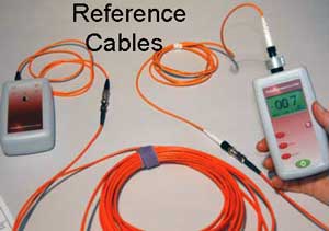
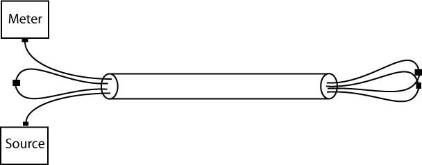
Reference Test Jumper
Cables and Mating Adapters
- In order to test
cables with a power meter and source or with an OTDR, one
needs to
establish test conditions. The test
conditions are similar to how the actual cable plant will be used
when communications equipment is connected (see below.) For
insertion loss
testing, this requires reference launch
jumper
cables to connect the test source to the
fiber in the cable under
test and receive cables to connect the fiber
optic
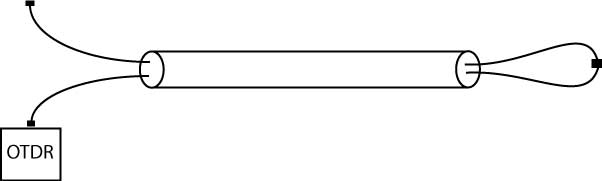
power meter. For OTDR testing, this requires
a reference launch cable to connect the OTDR to the fiber in the cable
under test and a receive cable at the far end of the fiber.
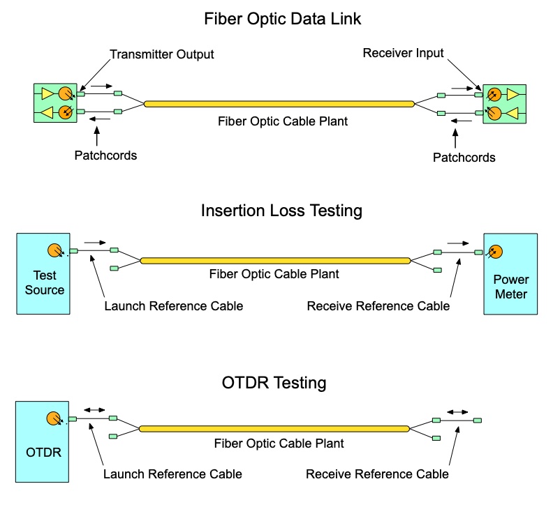
Reference cables used with test equipment
function similarly to the patchcords used connect the communications
equipment to the cable plant. A fiber optic test source is similar to
the transmitter of a datalink and an optical power meter is similar to a
receiver, so the test made with the source and meter, called an
insertion loss test, tests a fiber in the cable plant in a manner
similar to how it is used when operating as a data link. Thus the
reference cables can be considered substitutes for the patchcords. The
launch cable can be used to set the test conditions, including modal
conditions in multimode cable, and the reference connector on the launch
cable mated to the connector on the fiber under test is used to test
the quality of that connection. At the far end, the receive reference
cable connector tests the connector on the cable under test and connects
to the meter to measure the loss.
An OTDR tests the fiber differently, using the backscatter from the
fiber to create a snapshot of the fiber. See below. (For more information on OTDR
testing, read the section on the FOA Guide on OTDRs.)
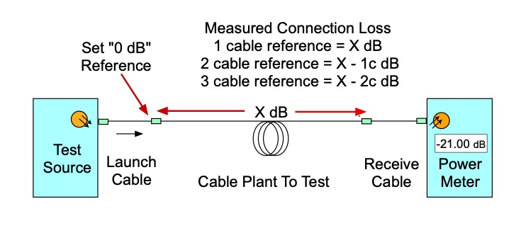
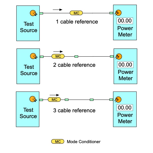
- Reference Cables For Insertion Loss Testing (see diagram above)
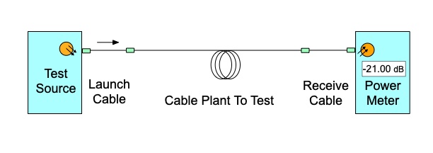
- Insertion loss testing may
require one,
two or three reference cables, depending on
the test performed and the appropriate mating
adapters for the connectors.
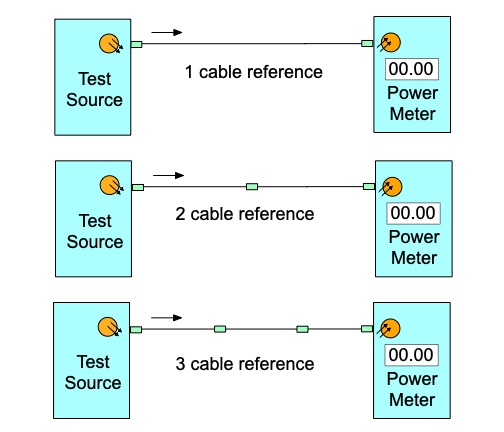
The 1 cable reference is used when the connector type on the instruments
matches the connectors on the cable plant, e.g. both use SC connectors.
After setting the 0 dB reference, the meter is disconnected and a
receive cable attached to it. The source launch reference cable is
connected to one end of the cable to be tested, the receive reference
cable and meter to the other end, and a measurement of loss is made.
This method is generally the preferred method of testing loss.
Note: Once the 0 dB reference is set, one should not disconnect the
launch cable from the source. Doing that will change the 0 dB reference
set and will require setting the 0 dB reference again.
The 2 cable reference can be used when the connectors on the instruments
and the cable plant do not match, e.g. SC connectors on the instruments
and LC on the cable plant. The reference cables will be hybrid cables,
SC on one end and LC on the other end. After setting the reference, the 2
cables are disconnected at the middle connection, attached to the cable
being tested and the loss measured.
The 3 cable method is used when the connectors on the instruments and
the cable plant do not match and/or the connectors on the cable plant
are plug/jack connectors such as the MPO connector with alignment pins
on one connector and holes on the mating connector. Here the two cables
on the ends are hybrid cables with connectors on one end to mate to the
instruments and connectors on the other end to mate with the 3rd
reference cable. The 3rd reference cable is a short cable with
connectors that are identical to the cable plant being tested. After the
0 dB reference is set using all 3 cables, the center cable is replaced
by the cable plant to be tested and the loss measured. This is sometimes
called a "cable substitution test."
The cable plant loss you measure will
depend on the reference method you use. The 2 cable method includes one
connection between reference cables when you set the 0 dB reference and
the 3 cable method includes two connections. The loss you measure with
the 2 and 3 cable reference methods will be reduced by the loss of the
connections included when setting the 0 dB reference.
Note: "1 c" is the loss of the connection when setting a 0 dB reference
with 2 cables and "2c" is the loss of the 2 connections included when
using the 3 cable reference method.
If the test requires mode
conditioning, such as with multimode fiber requiring a mandrel wrap or
encircled flux (EF) launch condition, the mode conditioning is done in
the launch cable attached to the source. Some multimode LED sources are
specified for EF launch and do not require mode conditioning.
- Reference cables for
insertion loss testing with a light source and power
meter are typically 1-3 meters long, with fiber and
connectors matching the cables to be tested.
- (OTDR reference/launch cables
are also used to isolate the large reflectance from
the instrument connector as well and need to be much
longer, typically ~20-100 meters for multimode and ~1
km for singlemode.)
- The
launch
and receive cables must be made with fiber
that is the same as the fiber in the cable plant being tested and
connectors matching the cables to be tested
and
terminated carefully to ensure low loss.
- The accuracy of the insertion loss
measurement will depend on the reference cables, since they will be mated to the
cable under test and the connection loss is measured
against the connector on the reference cable. To
provide reliable measurements, launch and receive
cables must be in good condition and kept very
clean. They can easily be tested against each other
to insure their performance. Connector mating
adapters are used to connect the cables under test
to the launch and receive cables. Only the highest
performance bulkhead splices should be used, and
their condition checked regularly, since they are
vitally important in obtaining low loss connections.
The quality and cleanliness of
the connectors on the launch and receive cables is
one of the most important factors in the accuracy of
loss measurements. Always test reference cables by
the patchcord or single ended method (FOTP-171,
reversing the cables to test connectors on both
ends) to make sure they are in good condition before
you start testing other cables with them.
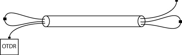
Reference Cables For OTDR Testing
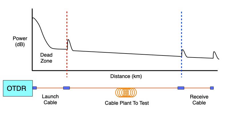
OTDR testing can be done with one or two reference cables. Each cable has a different purpose.
The
OTDR launch cable is used to overcome the "dead zone" of the OTDR caused
by the high power test pulse overloading the receiver circuitry. So the
launch cable must be long enough to allow the OTDR circuitry to recover.
This varies according to the range of the OTDR, the width of the test
pulse and the signal processing, but should be fairly long. For
singlemode long distance tests, at least a 1 km launch cable is
recommended. For short distance tests, like FTTH cables using high
resolution OTDRs, the cable can be as short as 50-100 meters. Multimode
cables are always short, so a cable of 50-100 meters is usually
adequate.
The purpose of the receive reference cables is to test the connection with the
connector on the end of the cable under test. That leads to the
requirement for a receive reference cable on the far end, a cable
sometimes called a "tail cord," a strange name from international
standards - does that make the launch cable the "head cord"?
Some OTDR tests are done with only
a launch cable if the test is to verify splices in a cable being
installed and segments spliced together and there is no connector on the far end..
Requirements For Reference Cables
- Fiber type matches fiber in the cable plant being measured
- Connectors can mate with
instruments and connectors on cable plant which may require hybrid
cables for 2 or 3 cable reference methods
- Cables for insertion loss measurements should be 1-3 meters long.
- Cables for OTDR testing should
be sufficiently long for the launch cable to extend beyond the OTDR dead
zone under test conditions and the receive cable be long enough to be
easily seen by the OTDR.
- Reference cables are low loss when measured against each other
- Testing requires compatible connector mating adapters
Fiber Type
The fiber type must match the type of fiber in the cable plant.
Singlemode reference cables will generally be G.652 fiber or G.657
bend-insensitive fiber. If the cable plant is very long and uses some
version of dispersion shifted fiber, the only effect of using G.652
fiber for reference cables is a small mismatch loss at the connections
on the ends. Multimode fiber is more sensitive, but while most cable
plants use 50/125 fiber and any version of 50/125 fiber can be used
(OM2/3/4/5), there are still cable plants using 62.5/125 multimode fiber
which cannot be tested with reference cables with any other fiber due
to the large mismatch losses, up to ~4 dB when going from 62.5/125 to
50/125 fiber. See FOA Guide page on mismatched fiber losses.
Recent updates in standards have approved using
bend-insensitive (BI) fibers for reference cables.With multimode cable
plants, virtually all recent installations use BI fiber anyway, so using
BI fiber reference cables is correct. Singlemode BI fiber is mostly
used for patchcords and for new high-density microcables and high fiber
count cables, but there appears to be no problem mating BI and regular
fiber for testing purposes.
Connectors And Mating Adapters
Reference cables must have connectors that can mate to the connectors on
the test equipment and cable plant under test. Some test equipment hs
fixed connectors (e.g. SC) while others have modular connector adapters
that allow changing the style of connectors. The big problem is often
the test equipment has SC conenctors, or even modular connectors for any
connector with a 2.5 mm ferrule, but many cable plants are now using LC
connectors with 1.25 mm ferrules. One solution is to use hybrid test
cables with SC connectors on one end and LC connectors on the other. Set
the reference with 2 cables and record the test method with the loss
data and/or compensate for the reference method.
Adapters that convert from SC to LC connectors are
available but they have some problems when used with testing. Some a
simple mechanical adapters, with mating sleeve with different hole sizes
on each side, These cab be highly variable in loss, especially with
singlemode fiber. Other adapters have fiber inside the adapter and are
more consistent, but they require compensation when used with test
equipment. Hybrid cables and a 2 or 3 cable reference method may provide
better results.
- "Special
Quality" Reference Cables
- Standards
groups have tried to specify the quality of
reference cables in terms of tight tolerance
components like the fiber and connectors.
Standards
which call for special reference quality
test cables specify specify cables with low loss connections. The
best recommendation for qualifying reference
cables
is to choose cables with low loss, tested
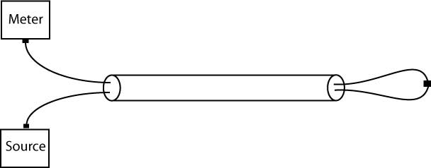
"single-ended" per cable test standard FOTP-171.
- Mode
Conditioning
Mode
conditioning is generally required for multimode and
singlemode launch cables attached to a source. Multimode
cables generally use a mandrel wrap mode conditioner (see
here and here)
and a LED source but special modal conditioning patchcords
are available. Singlemode fiber just needs a 30mm loop to
ensure the launch cable is singlemode.
- Mating Adapters
Connector-to-connector mating adapters are
used to
connect reference cables to the cables being
tested. For ferrule type connectors, the mating adapter is the critical
alignment device for the ferrules and is an important component in the
loss testing of a connection.
Only the highest quality mating adapters
should be
used for testing, as they are a factor in
loss also.
Inexpensive adapters generally have plastic
mating
sleeves to align the connector ferrules
which wear
out quickly, causing high loss with even
good
connectors. Use only mating adapters with
metal or
preferably ceramic mating sleeves which are
specified for both multimode and singlemode
connectors.
How Long Do Reference Cables And Mating Adapters Last?
Multiple matings will cause connectors to wear on the end
face and sometimes along the ferrules also. Most connectors are good for
hundreds or even thousands of matings as long as they are cleaned
regularly. Microscope inspection will show scratches or scuffing on the
connector endface, indicating wear may be a problem. Testing with a
single-ended loss test against each other with new mating adapters and
comparing results taken when they were new or last tested will show if
they are a problem. Mating adapters are harder to test, so they should
also be cleaned regularly using the probe type cleaners recommended for
jacks in patch panels and discarded after a number of matings - perhaps
500 for metallic alignment sleeves or several thousand for ceramic
alignment sleeves. If you notice connector ferrules getting dirty on the
side of the ferrule, change the mating adapters then.
Caring For Reference Cables
It
is very important to keep reference cables in good condition as they
are a very important factor in making accurate and repeatable fiber
optic measurements. Here are some guidelines for their care:
- Inspect and clean regularly
- Test against each other for loss
- Keep protective caps on connectors
- Store in safe place to prevent damage
- Do not kink, twist or otherwise stress
cables
- Repair or replace when needed
Field
Use - Creating Reference Cables When You Don't Have Them
You
should always use the proper cables for reference cables, but if
you
find yourself in the field without a set of
reference cables or your reference cables
are worn and causing high loss measurements, you can always use
patchcords or
other cables, even fibers in a cable you are
testing, as reference cables. Remember this
adds uncertainty to the measurements due to the condition
of the connectors and length of fiber.
OLTS
Testing
For a insertion loss testing of a multi-fiber cable with a meter and
source, you can use one fiber as a launch cable
and loop-back fibers from the far end of the
cable to test other fibers. You will need to take
the meter to the far end of the cable and calibrate
the output of the launch cable or use the 2-cable reference. It's easier to
do this with two sets of meters and sources, but can
be done with one.
Continue
looping
fibers back at the end of the cable. Remember each
loopback added includes the attenuation from two fiber
lengths and two connector losses!
OTDR Testing
If
you are testing a multi-fiber cable that's
long enough to test with an OTDR and you have
already tested it with an OLTS (like standards
require) so you know the fiber is good, you
can use one of the fibers in the cable as a
launch cable. Set up as below and simply have
another tech connect up the fiber being used
as the launch cable to the other fibers to
test each of them. If you want to test from
one end by yourself, loopback from the far end
and then use the two fibers as the launch
cable to connect up to other fibers from the
same end as the OTDR (second drawing.) If you
have access to both ends, you can continue
looping back and get many fibers on one trace,
to the length capability of the OTDR.
Additional Reading
Testing
Installed Cable Plants
Accuracy
of fiber optic measurements
|