Overview
of Fiber Optic Instrumentation
Testing fiber optic components
and cable plants requires making several
measurements with the most common measurement
parameters listed in the Table below. Optical power,
required for measuring source power, receiver power
and, when used with a test source, loss or
attenuation, is the most important parameter and is
required for almost every fiber optic test.
Backscatter and wavelength measurements are the next
most important and bandwidth or dispersion are of
lesser importance. Measurement or inspection of
geometrical parameters of fiber are essential for
fiber manufacturers. And troubleshooting installed
cables and networks is required.
Fiber Optic Testing
Requirements
| Test
Parameter |
Instrument |
|
Optical Power
(Source
Output, Receiver Signal Level)
|
Fiber Optic Power Meter |
|
Attenuation
or Loss of Fibers, Cables &
Connectors
(Insertion Loss)
|
FO Power Meter &
Source or
OLTS (optical loss test set)
|
| Source
Wavelength, Spectral Width |
FO Spectrum Analyzer |
|
Backscatter For
Loss, Length and Fault
Location)
|
Optical Time Domain Reflectometer(OTDR) |
| Fault
Location |
OTDR,
Visual Cable Fault
Locator
|
|
Bandwidth /
Dispersion
(MM:Modal &
Chromatic,
SM: Chromatic and Polarization Mode)
|
Dedicated
Bandwidth Testers |
| Reflectance |
OTDR,
OCWR (Optical Continuous Wave
Reflectometer) |
Fiber
Geometry
(Core and cladding diameter, concentricity,
etc.) |
Various
mechanical and optical inspection tools |
Standard Test Procedures
Most test procedures for fiber
optic component specifications have been standardized
by national and international standards bodies,
including TIA
in the US and ISO/IEC internationally. FOA
has its own standards for basic tests.
Procedures for measuring absolute optical power, cable
and connector loss and the effects of many
environmental factors (such as temperature, pressure,
flexing, etc.) are covered in these procedures.
In order to perform these tests,
the basic fiber optic instruments are the FO power
meter, test source, OTDR, optical spectrum analyzer
and an inspection microscope. These and some other
specialized instruments are described below.
Fiber Optic Power Meters
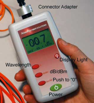
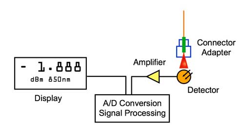
Fiber optic power meters measure
the average optical power out of an optical fiber.
Power meters typically consist of a solid state
detector (silicon for short wavelength systems,
germanium or InGaAs for long wavelength systems),
signal conditioning circuitry and a digital display of
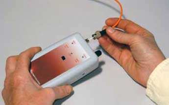
power. To interface to the large variety of fiber
optic connectors in use, some form of removable
connector adapter is usually provided.
Power meters are calibrated to
read in dB referenced to one milliwatt of optical
power. Some meters offer a relative dB scale also,
useful for loss measurements since the reference value
may be set to "0 dB" on the output of the test source.
Occasionally, lab meters may also measure in
linear units (milliwatts, microwatts and nanowatts.)
Since all semiconductor detectors have a sensitivity
that varies with the wavelength of the light it is
measuring, power meters are calibrated at the typical
wavelengths used in fiber optics, 850, 1300 and 1550
nm. Meters for POF systems are usually calibrated at
650 and 850 nm, the wavelengths used in POF systems.
Power meters cover a very broad
dynamic range, over 1 million to 1 or 60 dB. Although
most fiber optic power and loss measurements are made
in the range of 0 dBm to -50 dBm, some power meters
offer much wider dynamic ranges. For testing analog
CATV systems or fiber amplifiers, on needs special
meters with extended high power ranges up to +20 dBm
(100 mW). Although no fiber optic systems operate at
very low power, below about -50 dBm, some lab meters
offer ranges to -70 dBm or more, which can be useful
in measuring optical return loss or spectral loss
characteristics with a monochromator source.
Power meters measure the time
average of the optical power, not the peak power, so
the meters are sensitive to the duty cycle of an input
digital pulse stream. One can calculate peak power if
one knows the duty cycle of the input, by dividing the
average power by the duty cycle. For most loss
measurements, one uses a test source with CW (steady
state) or 2 kHz pulsed output. As long as the source
modulation doesn't change, no compensation needs to be
made. When testing link transmitter power or receiver
sensitivity, it is necessary to establish a standard
test pattern, generally a 50% duty cycle, called a
square wave, to allow accurate measurement of
transmitter output or receiver sensitivity. See
measuring power.
FO power meters have a typical
measurement uncertainty of +/-5% measuring absolute
optical power, when calibrated to transfer standards
provided by national standards laboratories like the
US National Institute of Standards and Technology
(NIST). Sources of errors are the variability of
coupling efficiency of the detector and connector
adapter, reflections off the shiny polished surfaces
of connectors, unknown source wavelengths (since the
detectors are wavelength sensitive), nonlinearities in
the electronic signal conditioning circuitry of the FO
power meter and detector noise at very low signal
levels. Since most of these factors affect all power
meters, regardless of their sophistication, expensive
laboratory meters are hardly more accurate that the
most inexpensive handheld portable units. Meters
should be recalibrated frequently by labs with NIST
traceable calibration systems.
See
calibration.
Measuring loss, which is a
relative measurement over a much smaller range of
optical powers has a much lower uncertainty. Generally
the instrument uncertainty is much smaller than the
uncertainty caused by the fiber optic components and
test setup.
(Photo courtesy Advanced Fiber
Solutions)
Fiber Optic Test Sources
In order to make measurements of
optical loss or attenuation in fibers, cables and
connectors, one must have a test source as well as a
FO power meter. The test source must be chosen for
compatibility with the type of fiber in use
(singlemode or multimode with the proper core
diameter) and the wavelength desired for performing
the test. Most sources are either LED's or lasers of
the types commonly used as transmitters in actual
fiber optic systems, making them representative of
actual applications and enhancing the usefulness of
the testing. Some tests, such as measuring spectral
attenuation of fiber requires a variable wavelength
source, which is usually a tungsten lamp with a
monochromator to vary the output wavelength.
Typical wavelengths of sources
are 650 or 665 nm (LEDs for plastic fiber), 850 and
1300 nm (LEDs for multimode fiber) and 1310 nm and
1550 nm (lasers for singlemode fiber). LED's are
typically used for testing multimode fiber and lasers
are used for singlemode fiber, although there is some
crossover, especially in high speed LANs which use
multimode fiber with lasers and the testing of short
singlemode jumper cables with LED's. The source
wavelength can be a critical issue in making accurate
loss measurements on long links, since attenuation of
the fiber is wavelength sensitive especially at short
wavelengths. Thus all test sources should be
calibrated for wavelength.
Test sources almost always have
fixed connectors. Hybrid test jumpers with connectors
compatible with the source on one end and the
connector being tested on the other must be used as
reference cables. This may affect the type of
reference setting mode used for loss testing.
Other source-related factors
affecting measurement accuracy are the stability of
the output power and the modal distribution launched
into multimode fiber. For extremely accurate
measurements, the source may need optical feedback
stabilization to maintain output power at a precise
level for long times required for some measurements.
Industry standards have requirements or
recommendations on the modal output of test sources
for multimode fiber that are aimed at the
manufacturers of the test sources. Mode scramblers,
filters and strippers may be required to adjust the
modal distribution in the fiber to approximate actual
operating conditions.
(Photo courtesy Advanced Fiber Solutions)
Optical Loss Test Sets/Test
Kits
The optical loss test set is an
instrument formed by the combination of a fiber optic
power meter and source which is used to measure the
loss of fiber, connectors and connectorized cables.
Early versions of this instrument were called
attenuation meters. A test kit has a similar purpose,
but is usually comprised of separate instruments and
includes accessories to customize it for a specific
application, such as testing a FO LAN, telco or CATV.
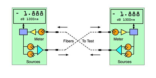
The OLTS may have several
optional features that affect its use. Some have
individual source outputs and meter inputs like a
separate power meter and test source, but may have two
wavelengths from one source output (MM: 850/1300,
SM:1310/1550.) Some offer bidirectional testing on a
single fiber and some have two bidirectional ports.
Some manufactures of premises copper cabling testers
offer modules to convert these testers to an OLTS,
allowing fiber and copper testing with one instrument.
The combination OLTS instrument
which contains both a meter and source may be less
convenient than an individual source and power meter,
since the ends of the fiber and cable are usually
separated by long distances, which would require two
OLTSs instead of one source and one meter. An OLTS
often has a single port for bidirectional measurements
also. This port usually has a fixed connector which
may cause problems when testing cable plants with
connector styles different than those on the
instrument, requiring a 2- or 3-cable reference for
loss testing which may not meet industry standards.
The bidirectional port may also have problems meeting
standards for modal power distribution in multimode
fibers. Ask the OLTS manufacturer about these issues
before purchasing an instrument.
Note: OLTS sometimes
display loss in a different way than if you test
with a meter and source. With a meter and source, if
you set the reference value for "0dB" at "0" and
test cables for loss, loss will be displayed as a
negative number, since lower optical powers (after
the loss) are more negative numbers. Some but not
all OLTS will display the loss as a positive number
which can be confusing to those who learn to test
using a source and power meter.
Optical Time Domain
Reflectometer
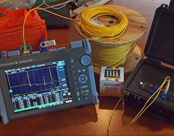
The optical time domain
reflectometer (OTDR) uses the phenomena of fiber
backscattering to characterize fibers and installed
cables, find faults and optimize splices. Since
scattering is one of the primary loss factors in fiber
(the other being absorption), the OTDR can send out
into the fiber a high powered pulse and measure the
light scattered back toward the instrument. The pulse
is attenuated on the outbound leg and the
backscattered light is attenuated on the return leg,
so the returned signal is a function of twice the
fiber loss and the backscatter coefficient of the
fiber.
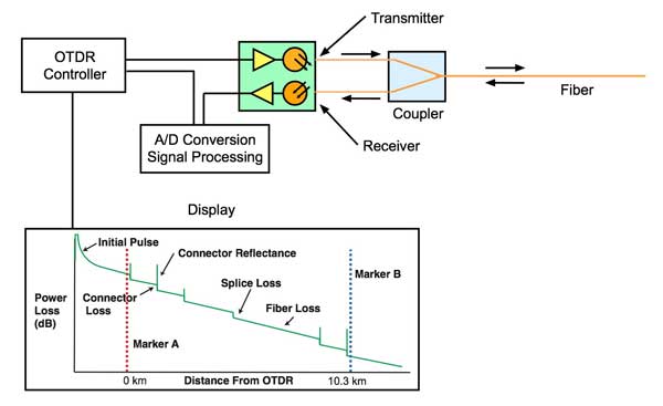
If one assumes the backscatter
coefficient is constant, the OTDR can be used to
measure loss as well as locate fiber breaks, splices
and connectors. In addition, the OTDR gives a graphic
display of the status of the fiber being tested. And
it offers another major advantage over the source/FO
power meter or OLTS, in that it requires access to
only one end of the fiber.
The uncertainty of the OTDR
measurement is heavily dependent on the backscatter
coefficient, which is a function of intrinsic fiber
scattering characteristics, core diameter and
numerical aperture. It is the variation in backscatter
coefficient that causes many splices to show a "gain"
instead of the actual loss. OTDRs must also be matched
to the fibers being tested in both wavelength and
fiber core diameter to provide accurate measurements.
Thus many OTDRs have modular sources to allow
substituting a proper source for the application.
While most OTDR applications
involve finding faults in installed cables or
verifying splices, they are very useful in inspecting
fibers for manufacturing faults. Development work on
improving the short range resolution of OTDRs for LAN
applications and new applications such as evaluating
connector return loss promise to enhance the
usefulness of the instrument in the future.
OTDRs come in three basic
versions. Full size OTDRs offer the highest
performance and have a full complement of features
like data storage, but are very big and high priced.
MiniOTDRs provide the same type of measurements as a
full OTDR, but with fewer features to trim the size
and cost. Fault finders use the OTDR technique, but
greatly simplified to just provide the distance to a
fault, to make the instruments more affordable and
easier to use.
More
on OTDRs.
Visual Cable Tracers and Fault
Locators
Many of the problems in
connection of fiber optic networks are related to
making proper connections. Since the light used in
systems is invisible, one cannot see the system
transmitter light. By injecting the light from a
visible source, such as a LED or incandescent bulb,
one can visually trace the fiber from transmitter to
receiver to insure correct orientation and check
continuity besides. The simple instruments that inject
visible light are called visual fault locators.
If a powerful enough visible
light ,such as a HeNe or visible diode laser is
injected into the fiber, high loss points can be made
visible. Most applications center around short cables
such as used in telco central offices to connect to
the fiber optic trunk cables. However, since it covers
the range where OTDRs are not useful, it is
complementary to the OTDR in cable troubleshooting.
This method will work on buffered fiber and even
jacketed single fiber cable if the jacket is not
opaque to the visible light. The yellow jacket of
singlemode fiber and orange of multimode fiber will
usually pass the visible light. Most other colors,
especially black and gray, will not work with this
technique, nor will most multifiber cables. However,
many cable breaks, macrobending losses caused by kinks
in the fiber , bad splices etc. can be detected
visually. Since the loss in the fiber is quite high at
visible wavelengths, on the order of 9-15 dB/km, this
instrument has a short range, typically 3-5 km.
Fiber Identifiers
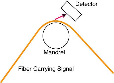
Telco technicians often need to
identify a fiber in a splice closure or at a patch
panel. If one carefully bends a singlemode fiber
enough to cause loss, the light that couples out can
also be detected by a large area detector. A fiber
identifier uses this technique to detect a signal in
the fiber at normal transmission wavelengths. These
instruments usually function as receivers, able to
discriminate between no signal, a high speed signal
and a 2 kHz tone. By specifically looking for a 2 kHz
"tone" from a test source coupled into the fiber, the
instrument can identify a specific fiber in a large
multifiber cable, especially useful to speed up the
splicing or restoration process.
Fiber identifiers can be used
with both buffered fiber and jacketed single fiber
cable. With buffered fiber, one must be very careful
to not damage the fiber, as any excess stress here
could result in stress cracks in the fiber which could
cause a failure in the fiber anytime in the future.
Measuring Fiber Bandwidth
Although fiber has a very high
bandwidth, some applications actually approach its
limits, requiring performance evaluation. Two factors
limit multimode fiber bandwidth: modal dispersion and
chromatic dispersion. Long singlemode links require
concern over chromatic dispersion or polarization-mode
dispersion. Specialized instruments are available for
testing each of these specifications but are expensive
and rarely used outside the laboratory.
O/E and E/O Converters
Optical to electrical (O/E) and
electrical to optical (E/O) converters have other uses
besides testing fiber bandwidth. O/E converters can be
used with high speed oscilloscopes to analyze pulses
in fiber optic links to see if the waveforms are of
the proper shape. This means measuring rise and fall
times of the pulse and the depth of modulation (the
difference between the peak power of the pulse and the
lowest power reached between pulses. They can be used
for testing lasers and LEDs used in transmitters and
link dispersion in long links. E/O converters are used
to test receivers for bandwidth and margin, usually in
conjunction with a bit error rate tester and
attenuator.
Optical Continuous Wave
Reflectometers (OCWR)
The OCWRor reflectance
tester was originally proposed as a special
purpose instrument to measure the reflectance
or optical
return loss of connectors installed on patchcords or
jumpers. Unfortunately, its purpose became muddled
between conception and inception. As actual
instruments came on the market, they had much higher
measurement resolution than appropriate for the
measurement uncertainty (0.01 dB resolution vs. 1 dB
uncertainty), leading to much confusion on the part of
users as to why measurements were not reproducible. In
addition, several instruments were touted as a way to
measure the optical return loss of an installed cable
plant, obviously in ignorance of the fact that they
would also be integrating the backscatter of the fiber
with any reflections from connectors or splices. Since
the measurement of return loss from a connector can be
made equally well with any power meter, laser source
and calibrated coupler, and an OTDR is the only way to
test installed cable plants for return loss, the OCWR
has seen little use in fiber optic testing.
Test Equipment For Long
Distance Fiber Links
Long distance fiber links may
suffer from chromatic dispersion or polarization mode
dispersion. Generally they also use DWDM so need
testing for spectral attenuation. These tests use very
specialized instruments. Read more about these tests here.
Optical Fiber Analyzers
There are many parameters of
optical fiber that require testing by the
manufacturer. These include attenuation (as a function
of source wavelength), bandwidth/dispersion, numerical
aperture and all the physical dimensions such as core
and cladding diameter, ovality, and concentricity.
Automated laboratory instruments are available to
measure all these parameters automatically, but many
fiber manufacturers prefer to build their own. The
most difficult part of fiber measurements is the fact
that subtle differences in test setup and
instrumentation can cause differences in measured
values.
Visual Inspection with
Microscopes
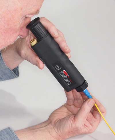
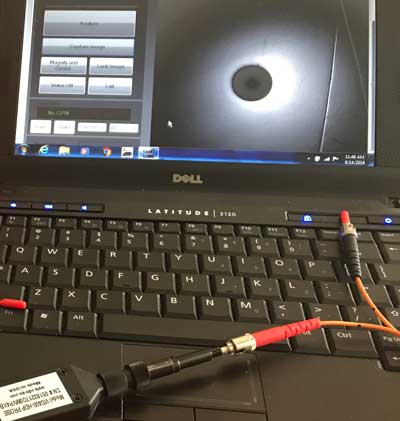
Optical (L) and video (R) microscopes
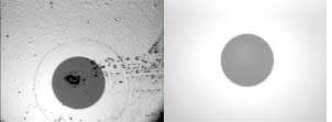
Cleaved fiber ends prepared for
splicing and polished connector ferrules require
visual inspection to find possible defects. This is
accomplished using a microscope which has a stage
modified to hold the fiber or connector in the field
of view. Fiber optic inspection microscopes vary in
magnification from 30 to 800 power, with 30-100 power
being the most widely used range. Cleaved fibers are
usually viewed from the side, to see breakover and
lip. Connectors are viewed end-on or at a small angle
to find polishing defects such as scratches.
Fiber Optic Talksets
While technically not an
measuring instrument, FO talksets are useful for FO
installation and testing. They transmit voice over
fiber optic cables already installed, allowing
technicians splicing or testing the fiber to
communicate effectively. Talksets are especially
useful when walkie-talkies and telephones are not
available, such as in remote locations where splicing
is being done, or in buildings where radio waves will
not penetrate.
The way to use talksets most
effectively is to set up the talksets on one fiber (or
pairs appropriate) and leave them there while all
testing or splicing work is done. Thus, there will
always be a communications link between the working
crew, which facilitates deciding which fibers to work
with next. The continuous communications capability
will greatly speed the process.
Recent developments in talksets
include talksets for networking multi-party
communications, especially helpful in restoration, and
system talksets for use as intercoms in installed
systems. There are also combination testers and
talksets.
There are no standards for the
way talksets communicate. Some use simple AM
transmission, some FM and some proprietary digital
schemes. Thus no two manufacturers' talksets can
communicate with each other. Bellcore has addressed
this matter in a technical advisory that proposes a FM
method at 80 and 120 kHz, but it will take years
before a standard has been set and manufacturers offer
compatible instruments.
Attenuators
Attenuators are used to simulate
the loss of long fiber runs for testing link margin in
network simulation in the laboratory or self-testing
links in a loopback configuration. In margin testing,
variable attenuators are used to increase loss until
the system has a high bit error rate. For loopback
testing, an attenuator is used between a single piece
of equipment's transmitter and receiver to test for
operation under maximum specified fiber loss. If
systems work in loopback testing, they should work
with a proper cable plant. Thus many manufacturers of
network equipment specify a loopback test as a
diagnostic/troubleshooting procedure.
Attenuators can be made by gap
loss, or a physical separation of the ends of the
fibers, inducing bending losses or inserting
calibrated optical filters. Both variable and fixed
attenuators are available, but variable attenuators
are usually used for testing. Fixed attenuators may be
inserted in the system cables where distances in the
fiber optic link are too short and excess power at the
receiver causes transmission problems.
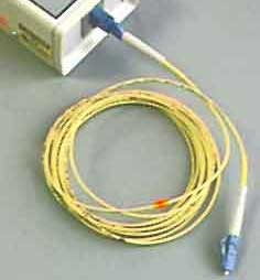
Reference Test Jumper Cables
and Mating Adapters
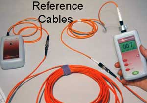
In order to test cables in an
insertion loss test, one needs to establish test
conditions. This requires reference launch jumper
cables to connect the test source to the cable under
test and receive cables to connect the fiber optic
power meter. For accurate measurements, the launch and
receive cables must be made with fiber and connectors
matching the cables to be tested and terminated
carefully to ensure low loss. To provide reliable
measurements, launch and receive cables must be in
good condition and kept very clean. They can easily be
tested against each other to insure their performance.
Connector mating adapters are used to connect the
cables under test to the launch and receive cables.
Only the highest performance bulkhead splices should
be used, and their condition checked regularly, since
they are vitally important in obtaining low loss
connections.
Additional Reading
Testing
Installed Cable Plants
Accuracy
of fiber optic measurements