Premises
Cabling Jargon
The key to
understanding any technology is understanding the language of
the technology the jargon. This page is an overview of cabling
jargon to introduce you to the language of the technology and
help you understand what you will be reading in this section. We
suggest you read this section carefully to help your
understanding of the rest of the pages and refer back to it when
you encounter a term that you do not
recognize.
What
is Premises Cabling?
By
premises cabling, we mean the cabling used inside buildings (and
in restricted geographic areas like campuses or among business
facilities) that follows industry standards. Mostly we are
refering to structured cabling systems defined by TIA-568 or
ISO/IEC 11801 and related standards that are used for
LANs, telephone systems and even other systems adapted to
structured cabling like CCTV, security or building management.
Other systems that depend on cabling such as security and
building control are migrating to structured cabing for its
widespread availability and predictability.
- Here's
an overview of the basic jargon used in cabling.
-
- To
begin with, what do we call this technology of cabling?
People
call it lots of things:
VDV (for
voice/data/video) cabling
Premises
(e.g. indoor) cabling
Structured
cabling (from the standards)
Data/voice
cabling
Low
voltage cabling (less than power cables)
Limited
energy cabling (mostly harmless)
Teledata
cabling (a made-up word from telecommunications and data)
Datacom
cabling (an abbreviated version of data communications)
- ....but
most people call it "premises cabling" for its application
or "structured cabling" after the "568" standard.
-
- Premises
cabling is the infrastructure for telephone and LAN
connections in most commercial installations and even in
some modern homes. It's also used for fire alarms, building
management, audio and video.
-
- Structured
Cabling is the standardized architecture and components for
communications cabling specified by the EIA/TIA TR42
committee and used as a voluntary standard by manufacturers
to insure interoperability.
-
- Networks
Cabling is
designed to provide connections for networks, primarily LANs-
local area networks - used for connecting Ethernet and WiFi
Devices.
Ethernet is standardized by IEEE 802.3 with versions for many
speed levels and cabling types
WiFi is a standard (IEEE 802.11) used for wireless
communications that has access points (antennas) connected on
Ethernet networks for wireless devices.
Network Architectures:
Most networks today use a "star" network, but prior networks
used busses or rings.
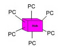
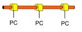
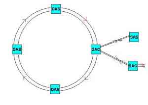
Star (L), bus (center) and ring (R) network architectures.
Networks today use the star network. Ethernet started as a bus
network on coax cable. IBM used the ring architecture on Token
Ring networks and it was later used for FDDI (fiber distributed
data interface.)
HFC:
Hybrid fiber-coax CATV network combines a fiber optic backbone
and coax drops to the subscribers.
- Read
more: Networks
-
- Cabling
Standards
- Structured
cabling is based on a number of industry standards -
voluntary interoperability standards - developed by
manufacturers who want their products to work together. They
meet in committees several times a year and decide on the
specifications of their products. These common specs mean
that equipment will work on any cabling system that follows
the standards and most cabling components can be
interchanged without adversely affecting performance.
Standards
are voluntary, written to ensure interoperability of
products from different sources, They are not legal
requirements like building or fire codes which are required
by local laws.
- EIA/TIA:
In the US, Electronics Industry Alliance/Telecommunications
Industry Association (TIA),
an industry trade association that creates voluntary
interoperability standards for the products made by member
companies. Worldwide standards rely on ISO
and IEC
standards. More.
- EIA/TIA
568: The main standard document for structured cabling,
usually referred to as simply "568." It is now on the "C"
revision, published in 2009. Worldwide, ISO/IEC 11801 which
came later than TIA, is approximately the same as TIA-568. More.
EIA/TIA
569: Covers pathways and spaces. Defines the "telecom
closet" or telecom room as it is now called. (ISO/IEC
14763-2) -
- EIA/TIA
570: For residential cabling.
-
- EIA/TIA
606: cabling system administration (documentation) (ISO/IEC
14763-1)
-
- EIA/TIA
607: Grounding and bonding
-
- Standards
are not code! They are voluntary interoperability
specifications. However every installation must be compliant
to local building codes for safety!
-
- NEC
(National Electrical Code): written by NFPA
(National Fire Protection Assn.) this code sets
standards for fire protection for construction and is a
legal requirement in most cities.
Read
More: Standards
-
- Structured
Cabling Architecture (TIA-568)
Traditional
structured cabling (above) defined in TIA 568 and adopted by
ISO/IEC 11801 includes UTP copper cabling and fiber optics,
including centralized fiber optics. The standards are based on
a maximum length of UTP cabling of 100 meters, 90 meters
installed in the building (the "permanent link") and 10 meters
of patchcords.
The
standards have been updated to recognize passive optical LANs
(POLs) based on fiber to the home (FTTH) technology (below)
using fiber optic passive splitters instead of electronic
network switches.
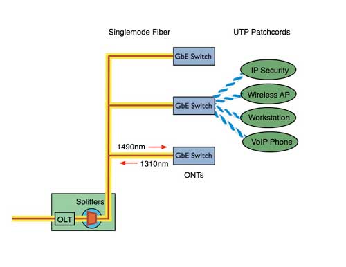
Passive
OLAN (optical LAN) using PON (passive optical network) from FTTH
(fiber to the home)
-
Structured
Cabling Terms:
The terms
listed her are the traditional terms used since the beginning of
structured cabling, but a new
set of terminology is being introduced. See below or the
link.
-
- Telecom
Closet (TC): The location of the connection between
horizontal cabling to the backbone. Now often called
"Telecom Room" to imply it's usually bigger than a closet!
-
- Main
Cross-Connect (MXC): The old telco term for the location of
the main electronics in a building. LAN people may call it
the equipment room
-
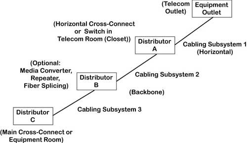
- Intermediate
Cross-Connect (IXC) : A room in between the TC and MXC where
cables are terminated
(TIA has
changed these terms to the ones in the diagram below but the
former terms are still widely used because they are well
understood and descriptive. Here
are the new terms.)
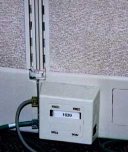
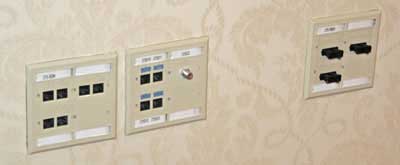
- Work
Area Outlet: The jack on the wall which is connected to the
desktop computer by a patchcord. Often integrated into
modular furniture.
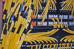
- Patch
Panel: A rack or box where cables are terminated - usually
in 110 punchdowns and interconected with patchcords
-
- Patchcord:
A short length of UTP stranded cable with a RJ-45 plug on
either end, used to connect hardware to the link or to
connect cables in a Patch Panel. Also a short fiber optic
cable with connectors uses for connecting cables or
equipment.
-
- Horizontal
Cabling: The connection from the telecom closet to the work
area outlet (desktop)
-
- Backbone
Cabling: The cabling that connects all the hubs in telecom
closets or MXCs together
-
- Link
(Permanent Link): The installed cable plant from work area
outlet jack to the patch panel in the telecom closet
(definition used for testing the permanently installed cable
plant.)
-
- Channel:
The cable plant including the link plus patchcords on either
end to connect the communications hardware (a definition
used for testing the installed cable plus patchcords
connecting equipment.)
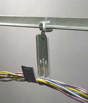
- J
hook: A hook shaped like the letter J used to suspend cables
-
- Fishtape:
Semiflexible rod used to retrieve cables or pull line
-
-
-
- Cable
-
- The
Types Of "Low Voltage" Copper Cable. Cabling standards cover
UTP (unshielded twisted pair), ScTP (screened twisted pair),
STP (shielded twisted pair) and fiber optics. Coax cable is
used in premises cabling for video, especially residential
TV or security.
- For
more information on fiber optic cabling, see the FOA
Online Fiber Optic Reference Guide.
-
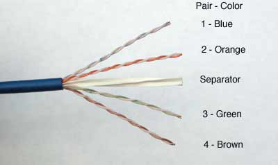
- UTP:
Unshielded twisted pair cable, is comprised of 4 twisted
pairs of copper conductors, graded for bandwidth as "Levels"
(from Anixter) or "Categories" (EIA/TIA 568). Legacy
analog phone systems (POTS or plain old telephone systems)
used multipair UTP cables with 25, 50, 100, 200 or more
pairs.
- A
typical Cat 6 UTP cable is shown below. Notice the
difference in the twist rates of the pairs - that difference
helps reduce crosstalk between the pairs at higher
frequencies.
-
-
- STP:
Shielded twisted pair, specified by IBM for Token Ring
networks and offered by some vendors in higher performance
versions than UTP.
ScTP:
Screened Twisted Pair, a UTP cable with an overall foil shield
to prevent interference.
Category-Rated
Cables: Category 3,4,5, 5e, 6, 6A, 8: Ratings on the bandwidth
performance level of UTP cable, originally derived from
Anixter's Levels program.
Cat 8 is a new short length cable for data center connections of
servers and switches.
"Categories" are called "Classes" in worldwide standards like
ISO and IEC. Cables rated Cat 5 or higher are limited to 4
pairs.
|
Characteristic
EIA/TIA(ISO)
|
Cat
5 |
-
Cat
5e
-
(Class
D)
|
-
Cat
6 (6A)
-
(Class
E)
|
-
"Cat7"
-
(Class
F)
|
Cat
8
(Class I, II)
|
| Supports
networks |
100Base-T |
1000Base-T |
-
1000Base-T
-
(10Gbase-T)
|
-
?
-
None
currently considered
|
-
10-40 Gb/s
|
| Test
Frequency |
100
MHz |
100MHz |
250
MHz
(500 MHz) |
600
MHz |
Terahertz |
| Length |
100
meters |
100
meters |
100
meters |
100
meters |
30
meters
|
| RJ-45
Compatible |
yes |
yes |
-
yes
|
No |
Some |
| Field
Tester Requirement: |
Level
2 |
Level
2e |
Level
3 (3e) |
Level
4
|
Level
2G
|
- Ethernet
at 10Mb/s and 100 Mb/s used only 2 pairs of the 4 pairs in a
UTP cable, but gigabit Ethernet required transmission on all
four pairs, as do all faster versions of Ethernet.
- Single
Pair Ethernet: IEEE has created a standard primarily for
industrial Ethernet that uses a single pair cable for 10,
100 or 1000Mb/s networks. It uses a different style of cable
and connector for rugged environments. A special
power-over-Etherent standard called PDL - power over data
line - has been developed for it also.
- Read
More:
UTP Cables
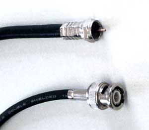
- Coax:
A type of cable that uses a central conductor, insulation,
outer conductor/shield, and jacket; used for high frequency
communications like CCTV (closed circuit TV) or CATV
(community antenna TV or cable TV).
- While
early LANs used coax cable for its additional bandwidth, it
is not included in TIA-568, but is included in TIA-570 for
home use.
-
- RG-6/RG-59:
75 ohm coax used for video. RG-6 is the standard for CATV,
RG-59 is used on some short CCTV networks.
-
- RG-58:
50 ohm coax used for "Thinnet" Ethernet.
Read More:
Coax Cable
Fiber
Optics:
Optical fiber carries signals as pulses of light over thin
strands of glass or plastic instead of copper wire.
- Optical
fiber is characterized by the size of the light-carrying
core and the cladding.
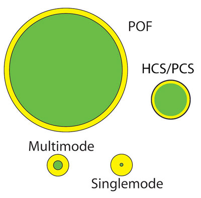
Multimode
optical fiber: larger core fiber used for short, relatively
low speed links (~<10G)
Singlemode
optical fiber: small core fiber used for longer distance
linkes with almost unlimited bandwidth.
HCS/PCS
- Hard-clad or plastic-clad silica fiber has a glass core and
plastic cladding. It is used for short, slow links.
Plastic
optical fiber (POF) large core plastic fiber used for short,
relatively slow links.
Fiber
Type
|
Core/Cladding
(microns)
|
Applications
|
OM1
|
62.5/125
|
Original
LAN fiber, now mostly obsolete
|
OM2/3/4/5
(G.651.1)
|
50/125
|
Most
widely used multimode fiber, laser optimized
|
Singlemode
(G.652)
|
9/125
|
Used
for all OSP links and high speed LANs, Passive OLANs and
data center connections
|
- Read
more: Fiber Optics
in Premises Cabling
- Terminations
- The
connectors for UTP are also standard - used on every cable
for Cat 3, 5, 5e, 6, but must be rated for the same
performance level, e.g. Cat 6 hardware on Cat 6 cable.
-
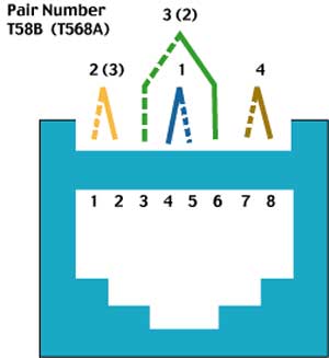
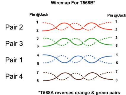
- RJ-45:
The popular name of the modular 8 pin connector used with
UTP cable in structured cabling systems. It is used
erroneously, as a connector is only really an RJ-45 if it is
terminated with USOC pinout for plain old telephone service
(POTS). Category rated terminations use the modular 8-pin
connector with the T568A or T568B pin configuration shown
above for better performance.
-
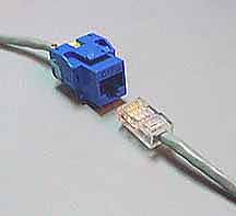
- Jack:
The receptacle for a modular plug like the modular 8
pin connector, often used in large quantities in patch
panels. (Left in the photo above)
- Plug:
The connector on the end of UTP cable. (Right in the photo
above.)
-
- Punchdown:
A connecting block that terminates two cables directly, most
often used for connecting incoming multipair cables to 4
pair cables to the desktop but occasionally for cross
connecting 4 pair cables. 110 blocks are most popular for
LANs, 66 blocks for telco, but some installers use BIX or
Krone.
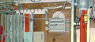
- 66
blocks on the left, 110 blocks on the right:
-
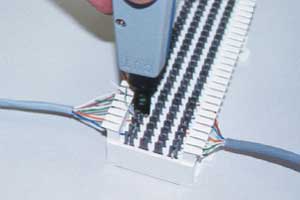 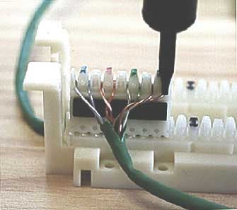
Using
punchdown tools to terminate a 66 block (left) and a 110 block
(right)
To
reduce crosstalk and signal loss, twists must be maintained as
close as possible to the terminations, with no more than 1/2
inch (13mm) of the pair untwisted.
Read more:
UTP Terminations
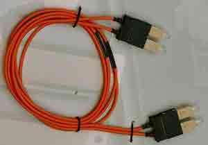
Optical
Fiber Terminations
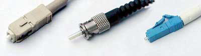
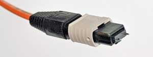
Fiber Optic
Terminations are generally (from left) SC, ST or LC connectors.
Multifiber links use MPO Connectors
Power
Over Ethernet
The IEEE
802.3 Ethernet committee created a standard for powering network
devices such as wireless access points, VoIP phones and
surveillance cameras off the copper pairs in a 4-pair UTP cable.
PoE
uses a 48 volt power supply and
requires cable of Cat 5 rating or higher. Power may be delivered
using what are called midspan
devices, dedicated PoE power
supplies that can be plugged into links or even patch panels, as
well or endspan devices, typically
switches designed to provide power as well as function as
anEthernet switch.
Power over
Ethernet Standards
Type
|
IEEE
Standard
|
Max
Current Per Pair
|
Number
of Pairs Used
|
Power
At Source
|
Power
At Device
|
PoE
|
802.3af
802.3at
Type 1
|
350
mA
|
2
|
15.4
W
|
13
W
|
PoE+
|
802.3at
Type 2
|
600
mA
|
2
|
30
W
|
25.5
W
|
PoE++
or 4PPoE
|
802.3bt
Type 3*
|
600
mA
|
4
|
60
W
|
51
W
|
PoE++
or 4PPoE
|
802.3bt
Type 4*
|
960
mA
|
4
|
99
W
|
71.3
W
|
- Copper
Cable Testing
-
- After
installing the cables, they must be tested. Every UTP, ScTP
or STP cable, including Cat 3 for telephones, must be tested
for wiremap, but cable "certifiers" will test
for all the parameters specified in the standards (listed
below.) A third type of tester, called a verifier,
tests the cabling to see if it will transmit date for
specific networks like Gigabit Ethernet.
Testing
for TIA568 cabling standards requires the use of a cable
certifier to confirm all the performance parameters of the
cabling.
Most
testing tests only the "permanent link," the cabling installed
in the building. Sometimes testing also requires testing the
"Channel" which includes the patchcords at either end.
-
- Wiremap:
All eight wires must be connected to the correct pins, and
the test is called a wiremap test.
-
- Length:
The length must be less than 90 m for the permanent link and
less than 100 m for the channel
-
- Attenuation:
The reduction in signal strength due to loss in the cable.
-
- NEXT:
Near End Cross Talk, or the signal coupled from one pair to
another in UTP cable.
-
- ACR:
Attenuation to crosstalk ratio, a measure of how much more
signal than noise exists in the link, by comparing the
attenuated signal from one pair at the receiver to the
crosstalk induced in the same pair
-
- Return
Loss: Reflection from an impedance mismatch in a copper
cable
-
- ELFEXT:
Equal level far end crosstalk; crosstalk at the far end with
signals of equal level being transmitted.
-
- Propagation
Delay: The time it takes a signal to go down the cable.
-
- DC
Loop Resistance: The DC resistance of the cable in ohms.
-
- Delay
Skew: The maximum difference of propagation time in all
pairs of a cable.
-
- Power
Sum Next: Near end crosstalk tested with all pairs but one
energized to find the total amount of crosstalk caused by
simultaneous use of all pairs for communication
-
- Power
Sum ElFEXT: ELFEXT for the sum of the other 3 pairs on the
4th pair.
-
- PSACR:
PowerSum ACR
Alien
Crosstalk: Crosstalk from one pair in a cable to the equivalent
pair in another cable, a problem with Cat 6A.
- Test
Equipment For Copper Cabling:
-
- Digital
multimeter: A simple tester that measures voltage, current
and resistance. It can be used to test if the cable is
shorted or open, often the only test used on coax cable.
-
- Wire
Mapper: Checks each wire to make sure they are terminated in
the correct order
-
- Cable
Certification Tester: Tests all specifications in the
standards: wiremap, length, attenuation and crosstalk in one
connection, gives you a pass/fail result
- Cable
Verification Tester: A device that runs network signals over
installed cabling to see if the cabling can transmit network
data without error. Does not test specifications for
standards.
- TDR:
Time domain reflectometer, a testing device used for copper
cable that operates like radar to find length, shorts or
opens, and impedance mismatches
Read
More: UTP Testing
- Fiber
Optic Cable Testing
- Testing
optical fiber is much easier. One need only tests
polarity/continuity and the loss from one end to the other,
as bandwidth or frequency response is not generally an issue
for premises cabling.
Fiber optic
testing is done with visual inspection microscopes to inspect
connector cleanliness and condition, visual fault locators for
tracing fibers and finding breaks, optical loss test sets
(OLTS) to measure insertion loss and OTDRs for troubleshooting.
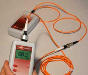
Light source and power meter (OLTS) testing the loss of a cable
Here is more
information on fiber testing.
-
- The
LAN Electronics That Makes It All Work Over The Cabling As
A Network
- Hub:
electronic box that connects to all the horizontal cables
which are them connected by backbone cabling, enabling any
PC to talk to any other, mostly replaced by switch.
-
- Switch:
A device like a hub but connects any two devices directly,
allowing multiple connections simultaneously
-
- Bridge:
A device that connects two or more sets of network cables
-
- Router:
A smart switch that connects to the outside world
-
- Ethernet::
A 10, 100 or 1000 Megabit per second local area network
(LAN) that is by far the most popular LAN. Ethernet::
A local area network (LAN) that is by far the most popular
LAN. Versions exist for transmission from 10Mb/s to
100Gb/s. All versions of Ethernet also have fiber optic
connection standards.
- Wireless
Is NOT Wireless
- All
LANs today include wireless access points. Wireless is by no
means wireless, as it requires wiring to connect it to the
network. It merely replaces patchcords with a wireless link
to allow roaming within a limited area. Wireless requires
many access points connected (over UTP cabling or fiber)
into the LAN Ethernet backbone. (See structured cabling
diagram above.)
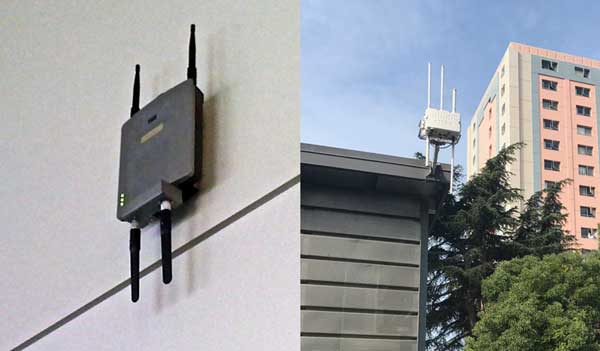
WiFI access
points indoors in a convention center and outdoors in a city
park
- WiFi
is the popular name for IEEE 802.11 standard used by most
portable computers and other mobile devices.
WiFi
access points in a LAN can usually be powered by PoE (power
over Ethernet, see above)
- Bluetooth
(IEEE 802.15) is a limited distance network for consumer
devices. It has been used to connect a wireless printer or
mouse to a PC, wireless headsets to cell phones and stereos,
cell phones to cars for hands-free operation, digital
cameras to printers, etc.
Dstributed
Antenna Systems (DAS): Indoor antennas for cell phones which may
use structured cabling. 4G, 5G and other cellular standards can
be brought indoors where 80% of all cell phone calls originate
using DAS. DAS can usually share cabling
Read
More: Wireless
Test your
comprehension with this quiz
Premises
Cabling Website Contents
Each page will open in a new window
Overview
of Premises Cabling and Standards
Jargon
Networks
UTP
Cables
Power Over Ethernet.
UTP
Terminations, (Tutorial).
UTP
Termination.
UTP
Installation VHO 66
Block, 110
Block, Jacks,
Plugs
UTP
Testing, UTP
Wiremapping
Coax
Cable VHO Coax
Termination
Fiber
Optics in Premises Cabling
Wireless
Design,
New T-568-C
Nomenclature
Premises
Cabling Installation
Glossary
Table
of Contents: The FOA Guide
|