Coherent
Communications Fiber Optic Data Links
The
purpose of this document is to define a coherent"
fiber optic datalink, its purpose, design and
performance. It is intended to provide guidance for
the designer of datalinks or communications systems
and the installer of fiber optic systems who must
verify the performance of the datalink including the "fiber
characterization" of the cable plant installed
for its operation.
Coherent
communications are used for many systems above 100Gb/s,
and almost exclusively for OSP long haul links. Laser
sources have a limit on the speed of direct modulation,
typically around 25Gb/s, limiting the lower cost,
simpler direct modulation data links to that speed.
Higher speeds are obtained by wavelength
division multiplexing of multiple 25Gb/s signals
on singlemode fiber or, in the case of some premises
multimode links, running parallel fibers of 25Gb/s
signals. Coherent transmission is much more complicated
but becomes cost effective for many OSP links because of
its superior reach without amplification, although it is
compatible with
fiber amplifiers when necessary to extend link
length.
Coherent
transmission is compatible with all types of fiber, but
on long links, the usual G.652 fiber is usually replaced
with G.654 fiber with large area cores to obtain the
lowest possible loss.
Datalinks - Direct Modulation vs. Coherent
A fiber optic datalink is a communications subsystem
that connects inputs and outputs (I/O) from electronic
subsystems and transmits those signals over optical fiber.
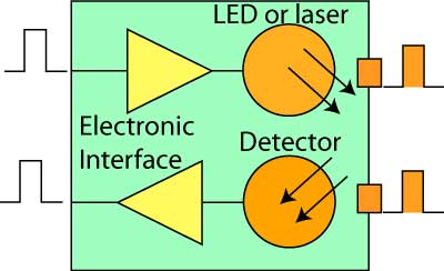
A
fiber optic datalink consists of fiber optic transceivers
or individual transmitters and receivers at either end
that transmit over optical fibers.
Direct Modulation
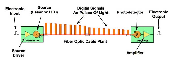
A direct modulation fiber optic datalink gets an
electrical pulse input from an electronic system. In the
transmitter, a source driver sends current through an
optical source, typically a laser, which creates a pulse
of light. The pulse of light from the source is coupled
into an optical fiber that is part of a fiber optic cable
plant. The pulse travels down the fiber where it is
attenuated by the fiber and suffers loss from fiber joints
created by splices or connections. As it travels along the
fiber, it suffers dispersion, both chromatic dispersion
caused by the fiber interaction with the wavelength and
spectral width of the source, and polarization mode
dispersion, caused by the variation in the polarization
characteristics of the fiber. At the receiver, the light
pulse is converted to an electrical pulse by a
photodetector, amplified by the receiver circuitry and
converted to an electrical pulse compatible with the
communications equipment it connects.
Direct modulation datalinks are typically limited by the
ability to directly modulate lasers, around 25Gb/s, and
the bandwidth of receivers. Higher
speed links are obtained by wavelength
division multiplexing of multiple 25Gb/s signals
on singlemode fiber or, in the case of some premises
multimode links, running parallel fibers of 25Gb/s
signals. More
on fiber optic transceivers and their components
Coherent
Transmission
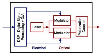
Coherent transmission uses much more complex transceivers.
Coherent transmitters overcome the limited bandwidth of
lasers when directly modulated by leaving the laser on all
the time and modulating it externally using two
electro-optical modulators. The modulators are not just
making ones and zeroes, but produce signals of 2 or 4
amplitudes to encode more than one bit of data in a single
pulse. The outputs of the two modulators are coupled as
two beams of different polarization which are multiplexed
on the same fiber. Thus the coherent transmitter can
encode optical data in the amplitude of the signal pulse
and in the polarization in the fiber, making it possible
to encode very high data rates.
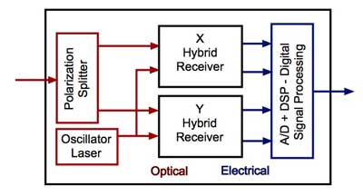
Coherent receivers use a technique used for electronic and
wireless transmission called a hetrodyne circuit that uses
a local oscillator to mix with an incoming signal to
demodulate the signal using techniques related to the
beats in acoustic mixed signals. Virtually all RF signal
transmission uses hetrodyne techniques. Hetrodyne
techniques are more complex with optics than electronics,
so the development of coherent receivers took many years
of R+D effort.
Two
other technologies were needed to facilitate coherent
optical communications, both electronic: high speed
analog-to-digital (A/D)/digital-to-analog (D/A)
conversion and digital signal processing (DSP). In the coherent
transmitter, the incoming electronic signal is
manipulated digitally to change the shape of the signal
to make it remove some distortions that will occur in
the transmission through the fiber. In the receiver,
after the incoming signal is split into the two
polarization components, mixed with the local oscillator
and converted to the electrical domain, it is digitized
and DSP algorithms are used to correct signal
degradation due to chromatic dispersion (CD) and
polarization mode dispersion (PMD) and extract the
amplitude modulation to reconstruct the signal. Since
the DSP must extract amplitude data from the waveform
which can be affected by noise, optical signal to noise
ratio (OSNR) is important. For that reason, coherent
systems often use ultra-low loss fiber like G.654 with a
larger mode field diameter.
As
can be seen from the block diagrams of coherent
transmitters and receivers, they are much more complex
than direct modulation transceivers. While a direct
modulation transceiver can be miniaturized to the size
of a SFP plug-in module, a coherent transmitter and
receiver is typically the size of a line card. Coherent
transmitters and receivers are also much more costly
than direct modulation transceivers but their advantages
for higher speeds and/or longer distances make them the
logical choice.
Coherent
links not only provide for higher speeds and longer
reach, but the DSP can also overcome some of the
dispersion problems created by transmission over long
lengths of fiber. CD is relatively easy to compensate
since it is predictable and constant. PMD compensation
is performed by the receiver DSP, but PMD is more
problematic. Since fiber polarization has a dependence
on the physical condition of the fiber and cable, PMD
tends to be variable with external stress on the fiber,
like wind on aerial cable, lighting strikes or large
ground vibrations such as earthquakes. Coherent
receivers can respond to changes in PMD within limits,
but large short period variations in PMD can be a
problem.
As
with other high speed links, the performance of the
cable plant is important to proper operation of the data
link. For direct modulation high speed long distance
links, the CD and PMD of the fiber are important because
while CD can be compensated, PMD cannot. Comprehensive
testing called fiber
characterization is done on the cable
plant for direct modulation systems to ensure the fiber
is within spec for the planned datalinks. One might
think that fiber characterization would be unnecessary
for coherent links, but that is not true. A 100G
coherent system can operate with fiber CD and PMD
performance adequate for 10G direct modulation, but that
still means many older fibers need the thorough testing
required for fiber characterization, including, of
course, inspection of all connectors to ensure they are
in good condition and clean.
Coherent
communications
used on long distance high speed
links work best on ultralow loss fibers which have
large mode field diameters, e.g. G.654 fiber.
Coherent links are sensitive to optical
signal-to-noise ratio (OSNR), so the lower loss in the
cable plant is preferable. As
a result, when characterizing fibers, accurate loss
measurements of these links is
important also.
Table
of Contents: The FOA Reference Guide To Fiber Optics