
Outside Plant Construction GuideIntroduction Review Of Fiber Optic Technology. Project Preparation And Guidelines. Underground Cable Construction. Underground Cable Installation. Aerial Cable Installation. Completing Outside Cable Plant Installation. Underground Cable Plant ConstructionUnderground cables are pulled in conduit that is buried underground, usually 1-1.2 meters (3-4 feet) deep to reduce the likelihood of accidentally being dug up. In extreme cold climates, cables may need to be buried at greater depths where there temperatures are colder and frost penetrates to greater depths. The process usually begins with digging a trench to bury the conduit which is generally PVC plastic pipe, sometimes with pre-installed innerduct (also called duct liner) with a pulling tape to facilitate the actual cable pulling process. Directional boring can also be used to avoid digging up the surface, for example in crossing streets or sidewalks. If the conduit and cables are all dielectric, as they usually are, a conductive marker tape should be buried above the conduit to assist in future cable location and as a warning to anyone digging in the vicinity of the cable. Conductive tape to be detectable should be no more than 300mm (12 inches) below the surface. This chapter covers many topics of relevance to OSP construction that should be considered as part of the overall project planning. For additional detail on the design, refer to the FOA online Guide material or the textbook on fiber optic network design. Dig Once Due to the disruptive nature of burying conduit, especially under roadways, many governments which grant permits for burying cable require the contractor to install extra conduits along the route to prevent having to dig again for any future cable installations. Since many cities have extensive conduits already buried for other services or may have required extra conduit to be buried during prior installations, conduit may be available for pulling new fiber optic cables.  Call Before You Dig 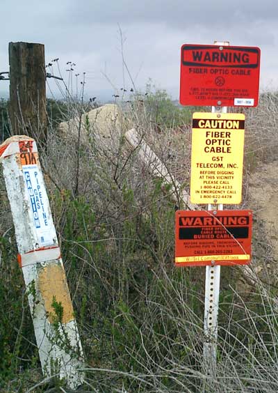 The old story about the most likely fiber optic communications system failure being caused by "backhoe fade" is not a joke it happens every day. But it reminds us that digging safely is vitally important. The risk is not just interrupting communications, but the life-threatening risk of digging up high voltage cables or gas lines. There are several services that maintain databases of the location of underground services that must be contacted before any digging occurs, but mapping these should be done during the design phase and double-checked before digging to ensure having the latest data. At the same time as the cable is installed, markers like these indicating its location and ownership can also be installed. Trenching Its immensely important for trenches to be excavated to such a depth that the crown of the duct has at least 800mm (32 inches) of backfill cover, in all soil conditions, except for where hard rock conditions are encountered. Where it is not possible to obtain the specified minimum trench depth, the client must be consulted. 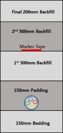 The trench depth in hard rock conditions can be relaxed (i.e. apply for a concession) to a minimum depth of 300mm (12 inches) backfill cover over the uppermost duct. But it then requires protection in the form of a concrete slab (either pre-cast, or cast in situ) placed on top of the padding material before backfilling. This concrete slab shall have a strength of 20 Mpa reinforced with high tensile wires and measure; 75mm (3 inches) thick by 300mm (12 inches) wide, and 900mm (36 inches) in length. 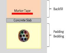 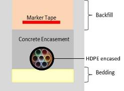
Concrete encasing is not endorsed enthusiastically by everyone; some argue that it turns a previously flexible duct into a long unreinforced concrete beam of little strength, prone to fracture with ground movement. And, this in turn could potentially damage an encased duct. A view not shared by everyone. Before pouring concrete, a slump test must be performed (take photos of this procedure). How do we measure the ideal slump? A slump of 10 cm or less is typically deemed acceptable (must not shear-off or collapse) - or as per client spec. Concrete that is poured too wet will be weak, regardless of how it is cured 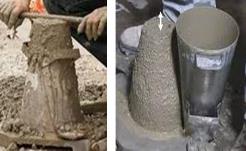
Trench Width One other obvious consideration is the width of the trench, which of course, is dependent on the duct diameter. Trenches that are too narrow will not allow for proper duct installation, whereas trenches that are overly wide are unnecessarily costly. On top of this, a too wide a trench will allow for too much duct snaking from the reel memory. Below are typical examples of proper trench sizing: 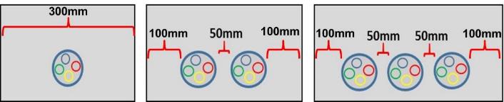 Areas where work is to be performed shall be cleared of all trees, shrubs, rubbish, and other objectionable material of any kind, which, if left in place, would interfere with the proper performance or completion of the contemplated work. Pilot Holes When the trench has been set out, pilot holes needs to be dug at 25 30 m (80-100 feet) intervals, particularly at points where the new trench crosses existing services. The pilot holes should be at least 150mm deeper and wider than the proposed trench. Pilot holes are one of the most effective methods utilized not only for the location of services, but also to determine the position of a trench, relative to other services. 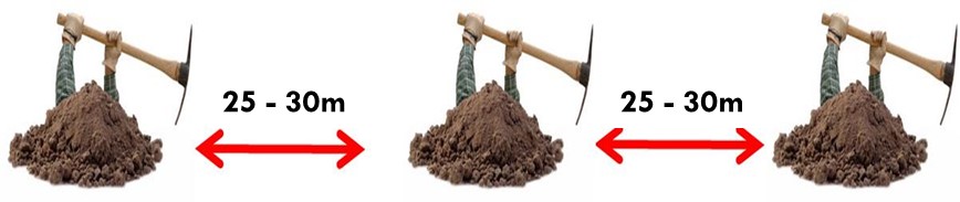 Location of Services The Contractor will generally be liable for any damages to existing services. It is the responsibility of the Contractor to locate all existing services. No excavation work should begin without having a copy of the approved wayleave/s on site. A utility representative can be asked to point out the position of a service and sometimes even oversee the work. Cable Locators can find the exact path and even estimate the depth of the utility service. Investing in a ground penetration radar (GPR) is the best investment for fail-safe trenching. They are used to identify underground services and formations although readings can be affected by the presence of high voltage power cables. 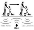 Ground Penetrating Radar Diagram Any trenching done in the vicinity of existing services should be done very carefully to prevent accidental damage to a service. Hand excavating is necessary to uncover known services prior to commencing with mechanical excavation. Any damage to existing services must be reported immediately to the project manager. Trenches Deeper than 1.2 meters Where the depth of a trench exceeds 1.2m and workers need to enter the trench, adequate measures must be taken by the contractor to provide support for this trench. No person must work alone in an excavation or trench that is greater than 1.2m deep. 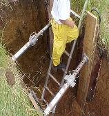 3 basic methods used for protecting workers against trench cave-ins are:
A ladder provides a safe means of access to the trench. Barricades and signs are to be used at safe distances from edges to protect unattended excavations. Machinery must never be placed in or near excavations and trenches where exhaust fumes may contaminate below ground atmospheres that workers are required to occupy. Care shall be exercised in the moving or removal of shoring to prevent the caving or collapse of the trench faces being supported. Suggested Trenching Practices (possibly not mentioned elsewhere)
 Barricading Construction 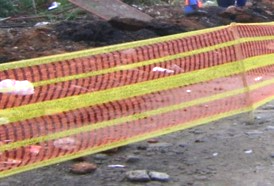
Trenching Near Curbs, Guttering, Paving and Driveway Crossings 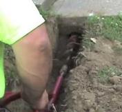
Road Crossings 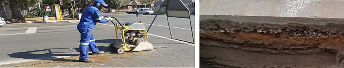
Stream and River Crossings 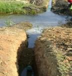 Before any serious thought is given to the installation of a high-density polyethylene (HDPE) duct at a river crossing, the network designer will consult with a geotechnical expert to conduct a comprehensive study. This investigation will reveal the most efficient way to accomplish the crossing in question. Horizontal directional drilling (HDD) (discussed later), has become a popular river crossing option, and as explained later, rightfully so. The duct must be sealed at both ends to prevent water or dirt ingress. Bridge Crossings 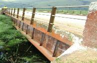 This work is typically undertaken by experts in this field. First and foremost, the use of existing ducts or service culverts within bridges must be fully explored. Not all bridge structures will have the exact same installation configuration and procedures may vary to accommodate your specific requirements. Ducts attached to the underside of bridges must not affect its load bearing capacity, reduce the clearance or cause other issues. The contractor shall inform the bridge owner 48-hours prior to the commencement of the work. The most common method to be used will involve the use of a hydraulically operated crane fitted with a safety basket be positioned adjacent to the bridge balustrade. From this position, workers wearing safety harnesses can be hoisted over the balustrade and lowered into a working position as required. Bracket mounting positions can now marked out on the side or underside of the bridge as directed by the design drawings and instructions. Next, drill the holes, fit the concrete anchors and mounting brackets and firmly secure them. The steel or ultra-high-density polyvinyl chloride (UPVC) base carrier duct can now be positioned and firmly secured. The microducts can then be pulled through the newly mounted base carrier. Use a continuous length of duct (no joints permitted). Where required and as stipulated in the design instructions, both the approach and departure ends may have to be encased in concrete where they traverse the bridge abutments and enter the ground. It is desirable of course, for the end-product to be both safe and visually appeasing. Trenching Near Power Cables Where no physical barrier exists, no duct or cable shall be laid within a distance of 600mm (24 inches) measured horizontally, nor cross within a distance of 300mm (12 inches) measured vertically from any high voltage power cable. Where this separation is compromised, the duct or cable must be separated by concrete slabs. 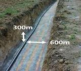 The standard protection slab is 900mm x 300mm x 75mm (36 x 12 x 3 inches) thick. This slab will be reinforced with 3.55 mm (1/8 inch) high tensile wires. 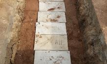 Rock Blasting Blasting for excavation shall not be performed without written permission obtained in advance, from the agency having jurisdiction. Procedures and methods of blasting shall conform to all local laws and ordinances. It is the responsibility of the Contractor to establish appropriate safety and health practices and determine the applicability of regulatory limitations prior to blasting. 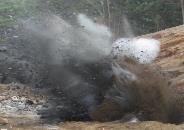 Duct Deviation 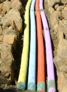 Handholes and manholes typically facilitate changes in direction. However, ducts may deviate from a straight line provided that individual lengths may be offset by no more than 35mm (1.4 inches), the offset is in the same direction, this to avoid creating S-bends and the maximum overall deviation between MHs / HHs does not exceed 15˚. Spacers should be used when placing multiple ducts in a trench. They prevent ducts from twisting over and around each other. By keeping the ducts in straight alignment, cable jetting and/or pulling tensions will be reduced. Steep Gradient Trenching 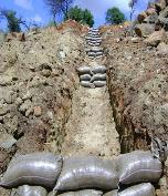 Where excavations needs to be done on inclines, a layer of sand bags should be placed at regular intervals (5m apart), to prevent the possible wash away of backfill material. Always consider the risks of land stability or earth movement, when trenching on embankments (specialist technical investigation may be required). Tree Roots 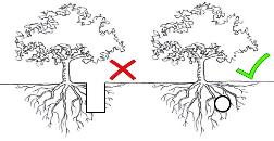 Prior to undertaking tree/bush/shrub clearing/cutting as may be necessary for trenching, approval in writing from the relevant authority and/or property owner needs to be obtained. Tree roots exposed while trenching must not be cut unless absolutely unavoidable. Never cut roots over 25mm in diameter, unless advice has been sought from the local authority. Ducts are to be sleeved in a HDPE pipe, if not 100mm away from existing tree roots. Surface Material Surface material (paving slabs, soil, grass, etc.) removed for construction must be kept apart by placing them on opposite sides of a trench, where they are least likely to interfere with traffic, pedestrians and drainage systems.Mow-able lawn shall be cut in square blocks and put aside and be kept moist until reinstated. Where trenches pass through gardens, the contractor shall seek direction from the owner. 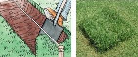 Duct Un‐Coiling and Installation Process Duct un-coiling can be accomplished by pulling the conduit straight into a trench from a stationary rotating de-coiler or by laying the conduit into the trench from a forward moving de-coiler positioned on a trailer. Ducts shall not be un-coiled without the use of a Vertical or Horizontal De-Coiler. De-coilers will prevent twisting, bending or kinking from occurring during the installation process. 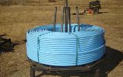 Once the duct coils are secured inside the de-coiler, only then can the containment straps on the duct coil be cut. Next, rotate the de-coiler slowly to unwind the duct out in one plane. Generally, the ducts are placed in the trench, one length at a time and joined on the floor of the trench using couplers. As the ducts are laid and jointed, install end caps on ducts at all MH/HHs to prevent water and dust from entering. Care shall be taken to ensure that no dirt collects between the duct and coupler to deliver an airtight seal. Ducts shall be laid in a straight line between MH/HHs. It is never ideal to have directional changes, but if unavoidable - keep the bending radius as big as possible and offset is in the same direction. At MHs or HHs where the duct goes straight-through, allow for sufficient slack for the duct to be secured against MH or HH walls. Duct Installation - Moving Trailer Method This method is most efficiently used where the path to be followed does not contain any obstructions that require the duct to be placed under. Move the trailer slowly along the trench route while unwinding and placing the duct in the trench. Take care not to over spin the reel. Duct Installation - Pulling Method The duct can also be pulled and placed by hand or by a mechanical pulling machine with the help of a pulling device that is fitted in‐between duct and mechanical pulling machine. the two types of pulling attachment devices most commonly used are a pulling grip or basket grip. Filling The Trench A typical trench will be filled with the materials shown in the diagram below. Bedding and Padding Bedding is the material constituting the even floor of an excavated trench onto which ducts are laid. The bedding should be raked if necessary to ensure it is level. Padding the the layer of material covering the ducts. The material used for bedding and padding must be of a granular, non-cohesive nature, graded between 0.6 mm and 13 mm, or as per client spec. It is desirable to pass both bedding and padding through a sieve before putting it back in the trench. 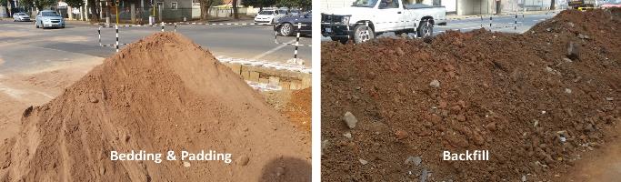 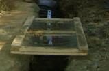 Care shall be taken to place padding material simultaneously on both sides of the duct to prevent lateral movement. The compaction of padding shall be executed manually using a hand tamper. Duct buckling is much more probable when the padding material does not provide adequate side support. Backfill and Warning Tape After the padding is tamped, backfilling of the trench can be done. Material excavated from trenches may be used as backfill, provided that it contains stones no greater than 150mm ( 6 inches) in diameter, trash, or organic matter that could potentially damage ducts. Backfill material is to be installed in layers not exceeding 300 mm (12 inches), with each layer compacted before the next is added. After compacting the first layer of backfill, the warning or marking tape is placed. Take photos of this procedure as proof of existence. Hopefully, the warning tape will be encountered before damaging any ducts or cable. 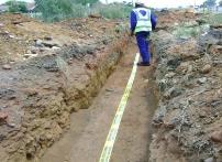
Backfilling (Concrete)  Before filling the trench with concrete, check the consistency of the concrete (slump test). Tamper the concrete using special care not to damage the ducts. Check for cavities in the concrete. Allow for the concrete to cure (harden). As mentioned earlier, some contractors believe a concrete backfill turns a once flexible duct into a long unreinforced concrete beam of negligible strength, very likely to fracture with ground movement. This in turn could potentially damage the duct. This view is not shared by everyone. Trench Compacting 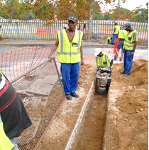 Once a poorly compacted layer is in place, it is difficult if not impossible to achieve good compaction in the layers above. This is a key point; a consequence of poor backfill compaction is high percentage of air voids. Manual compaction is performed until the ducts are covered by both a 150mm layer of padding and 300mm of backfill, at which point a vibratory plate compactor can be used. The compaction of the final backfill layer shall be by means of a compaction machine and shall be compacted to a density higher than or at least equal to that of the virgin soil parallel to the trench. After completion of the backfill, a DCP test must be done. This test must be documented. Optimum Moisture Content (OMC) 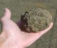 Moisture conditioning of the backfill material shall be carried out by the contractor. If not specified by the client, the following 2 Field Tests for Optimum Moisture Content (OMC) can be used: A handful of backfill tightly squeezed in the hand, shall be wet enough so that it binds together with no more than slight crumbling when the hand is opened. Dynamic Cone Penetrometer (DCP) Testing
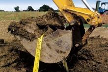
 Micro-trenching 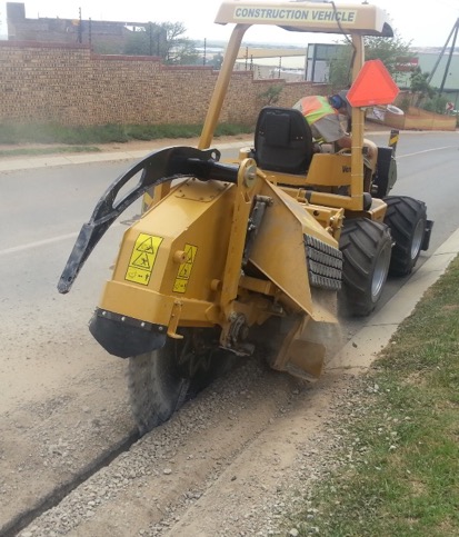 The time-honored method of burying ducts involves digging trenches with a backhoe or a pick and shovel brigade. Alternative methods of deploying underground fiber cables includes using storm water drains and sewers, while another is micro-trenching, which involves using a machine cut a narrow slot in the road surface. The benefits of micro-trenching are less disruption to roads and sidewalks, faster deployment and more cost effective trenching. Microtrenching is also highly effective with microducts and blown microcables. A single groove can hold a 6-duct microduct that can allow installation of 144 or 288 fiber cables. If only one cable is needed at the time of construction, adding cables in the future can be done without additional construction. Depending on the type of road and the depth of existing services, the micro-trench can be anything from 20 mm to 60 mm (0.8 to 2.5 inches) wide and, 300 mm to 500 mm (12 to 20 inches) deep, usually near the edge of the roadway. The machine has a blade in front (much like a giant angle grinder) which cuts into the road surface. Horizontal Directional Drilling (HDD) HDD is a drilling process where a drill head is steered underground. This method is adopted by all companies but generally sub-contracted to specialists. HDD is the preferred method to cross roads, highways, railway lines, rivers and all other services that may prove to be too dangerous or costly to cross using conventional methods like trenching and/or ploughing. Rigs capable of drilling up to 300 metres (1000 feet) in one drill are available and various sizes of ducts can be installed with this equipment. 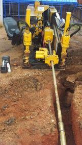 The depth of any hole drilled for the installation of a new service, must be at least 800 mm (32 inches) below surface of the road, or as per client spec. At river crossings the distance between the bottom of the water and the drilling hole should be 10-times the diameter of the pipe and not less than 3 m (10 feet). If the accuracy of the drilling is not specified in the wayleave, the area in which the drilling may wander should not exceed a 40mm (1.6 inches) diameter around the predetermined axis. 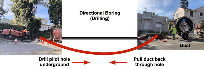 The HDD process involves 3 installation stages: pilot drilling, reaming the pilot hole and pulling the duct into the reamed hole. The course of the drill is monitored and can be controlled as rods progress following an upward sloping path, before emerging at an intended point. The drill head is then removed and replaced with a back reamer, ± 20% larger than the duct or cable to be pulled into the hole. The duct is attached to a swivel connection on the back reamer. The drill-rods and reamer are rotated and pulled through the hole, enlarging it and pulling-in the duct at the same time. The whole operation is carried out with pressurized drilling mud, which both carries away the spoil and supports the hole. The covering must not be less than three times the final diameter of the drilling hole and at a minimum of 1.5m (6 feet). Soil removal during the drilling process is the responsibility of the contractor. As always, the location and depth of underground services must be pre-determined before drilling can commence - as sudden deviations are not possible to bypass obstacles. Direct-Buried Installations On paper, direct-bury is fairly simple and very cost-effective - you dig a trench, install the cable and re-instate. However, once in the ground, it is perhaps more susceptible to damage from unrelated digging activities than cable in a duct, and much more importantly, it is difficult to access and repair. 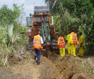 In general, plowing-in the direct burial cable is the most desirable and economical method of cable placement in open or rural areas where there likely to be fewer obstacles to impede the progress of the plowing equipment. In urban or sub-urban areas where there can be many obstacles such as underground utilities, sidewalks, road crossings etc., trenching has advantages. On all direct-buried installations, armored cable must be deployed -which provides for both crush protection and prevention of rodent penetration. 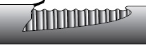

If only an armored cable is to be placed, a trench no wider than 375 mm (15 inches) will do. The trench should be 1.2 m deep (4 feet) or as stipulated in the wayleave. Grade off abrupt changes in terrain ahead of the plough. Excavate at least 5 m at the starting point, to allow for the plough to immediately lay the cable at the correct depth. Always start the plough tractors movement slowly and increase speed gradually only after the cable slack is taken up from the cable delivery system. Ploughing operations must be observed continuously for obstructions, proper feeding of the cable, specified depth, following of the marked route, and the safety of the crew. Stoppages in the plough-in process should only be for the loading of cable or marker tape and when the terrain demands for this. Warning Tape must be placed approximately 300 mm below the ground surface, directly above the cable. It is critically important for manholes and hand holes to be built only after the plowing-in of the cable. Pre-fabricated man holes and hand holes are often utilized. Each section, after plowing-in, the cable must be checked with an OTDR for possible damage. After the plough in process is completed, the trench must be levelled by back blading with the plough-in machine or using a TLB to level the disturbed areas. Armored Cable Grounding (Earthing), Bonding and Surge Protection The National Electrical Code (NEC) recommends that non-current carrying armour shields and metallic strength members be bonded and grounded. Proper grounding and bonding is required for the safe and effective dissipation of unwanted electrical current, and it promotes personal and site safety. Typically, optical fiber cables do not carry electrical power, but the metallic components of a conductive cable are capable of transmitting current. When the armoured cable is correctly bonded and grounded, it minimizes the risk of unwanted electrical current that could potentially harm personnel, property or equipment. Required By electrical codes and equipment manufactures | To protect personnel and equipment The armoring of optical fiber cables shall be lugged and bonded to an earth bar using a soft multi-stranded 6 mm² green / yellow insulated bonding cables. Bonding cables shall be kept as short as practically possible and must contain no sharp bends. Note: The difference between the terms bonding and grounding: · Bonding is the multiple connections to metallic parts (at every joint), required to form a continuous electrical path. · Grounding is the act of connecting that path to an earth. The Procedure Use a cable knife to score the outer sheath of the armoured cable approximately 25 mm (1 inch) long. Take care not to damage the inner sheath. 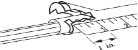 Slide the base plate under the armour. 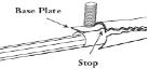 Place the top plate over the base plate and tighten down the lock nut. 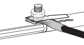 Cover the grounding clamp and split portion of the sheath with vinyl tape and connect to the ground system or bond thru. 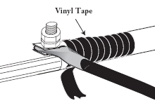 Underground Cable Markers 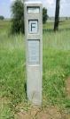
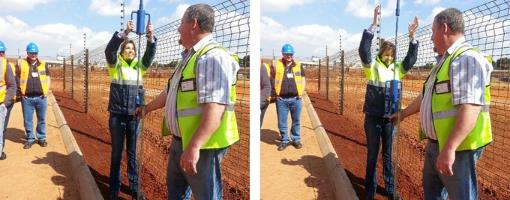
In 'non-built-up areas' underground routes must be marked with identifiable markers. GPS coordinates of all MHs /HHs must be taken and documented to form part of the as-built documents. These markers shall have a length of not less than 1.8 m and a diameter of not less than 100 mm. Markers shall be planted 600 mm deep, opposite a MH or HH and be well compacted. Passive markers can also be buried at key points during construction or used to mark existing facilities. Manholes and Handholes Manholes (MH) and handholes (HH) shall be positioned as far away as possible from road junctions. MHs and HHs must to be built according to prescribed dimensions and specifications. 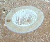
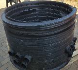 Before any concrete is placed the Contractor shall examine the shuttering for firmness and correctness of position and remove all dirt and other foreign matter. Hand mixing of concrete is permitted in exceptional cases but only with written permission of the client. Concrete mix shall be such that a strength of 20MPa (2.5:2.5:1) is obtained 28 days after pouring. Duct entry points into HHs / MHs must be drilled, without cracking or damaging the surrounding structure. Ducts shall enter and exit HHs / MHs in line with the direction of the route, for them to be coupled thru without any obvious effort, as a continuous duct. HH / MH external labeling should be done on the coping and NOT the lid, as lids can get damaged and be replaced. GPS coordinates for the location must be recorded. On completion of a HH / MH, the Contractor shall re-instate the area around the HH / MH to its original state or better. HH / MH covers shall be finished flush with the surface area. Where bricks are used to construct HHs the following must apply:
HH Installation
HH / MH Inspection
Safe HH / MH Working Procedures
Installation Underground In Other Services There are methods using robots to install fiber optic cable in storm sewers or other underground pipes. They have been used in center cities where construction is difficult but not widely. (C) 2018 The Fiber Optic Association Inc. Return to the OSP Construction Guide Index |
|
|