Fiber Optic
Splicing and Termination
Jump To:
Performance
Specifications/Loss
Performance Specifications/Reflectance
Splicing
Fusion Splices
Mechanical Splicing
Protecting Splices
Connectors
Termination
Procedures
Prefabricated
Cabling Systems
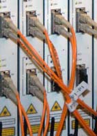
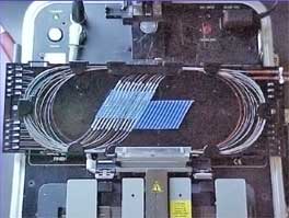
Fiber Optic
Connectors (L) and Splices in Splice Tray (R)
Fiber optic joints or terminations are made two ways:
1) splices which create a permanent joint between
the two fibers or 2) connectors that mate two fibers to
create a temporary joint and/or connect the fiber to a
piece of network gear. Either joining method must have
three primary characteristics for good optical
performance: low loss, minimal reflectance and high
mechanical strength. Terminations must also be of
the right style to be compatible to the equipment
involved and be protected against the environment in
which they are installed.
Splices are considered permanent joints and are used for
joining most outside plant cables. Fusion splicing is
most widely used as it provides for the lowest loss and
least reflectance, as well as providing the most
reliable joint. Virtually all singlemode splices are
fusion. Mechanical splicing is used for temporary
restoration and for most multimode splicing.
Connectors are used for terminations, that is the ends
of the fibers where they connect to equipment or to
patch panels where fiber routing can be changed by
patching different fibers together. Different connectors
and termination procedures are used for multimode and
singlemode fibers. Multimode fibers are relatively easy
to terminate, so field termination is generally done by
installing connectors directly on tight buffered fibers
using the procedures outlined below. Most field
singlemode terminations are made by splicing a
factory-made pigtail onto the installed cable rather
than terminating the fiber directly as is commonly done
with multimode fiber. Singlemode terminations require
extreme care in assembly, especially polishing, to get
good performance (low loss and reflectance), so they are
usually done in a clean manufacturing facility using
heat-cured epoxy and machine polishing.
Probably no fiber optic component has been given greater
attention than connectors. Manufacturers have come up
with over 80 styles of connectors and about a dozen
different ways to install them. There are only two types
of splices but numerous ways of implementing them.
Fortunately for both manufacturers and installers, only
a few types of either are the ones used for most
applications.
Performance
Specifications
Connector
and Splice Loss
The primary
specification for connectors or splices is loss or the
amount of light lost in the connection.
When we say
connector loss, we really mean "connection" loss - the
loss of a mated pair of connectors, expressed in "dB."
Thus, testing connectors requires mating them to
reference connectors which must be high quality
connectors themselves to not adversely affect the
measured loss when mated to an unknown connector. This
is an important point often not fully
explained. In order to measure the loss of
the connectors you must mate them to a similar, known
good, connector. When a connector being tested is
mated to several different connectors, it may have
different losses, because those losses are dependent
on the reference connector it is mated to.
Another
misconception concerns connectors that are installed
by splicing on the end of a fiber, wither by
mechanical or fusion splicing, or by splicing on a
pigtail. The connection loss of this type of
termination includes the typical connection loss
tested when mated to a reference connector plus the
splice used to attach the connector to the fiber, as
the splice is the attachment method and therefore
included in the connection loss. This is how standards
often list high losses for connectors because they
must include not only the direct attach
adhesive/polish connectors but also splice-on
connectors and array connectors with many fibers.
 Connection
and splice loss is caused by a number of factors. Loss
is minimized when the two fiber cores are identical
and perfectly aligned (more
on the effects of fiber geometry and alignment),
the connectors or splices are properly finished and no
dirt is present. Only the light that is coupled into
the receiving fiber's core will propagate, so all the
rest of the light becomes the connector or splice
loss. Connection
and splice loss is caused by a number of factors. Loss
is minimized when the two fiber cores are identical
and perfectly aligned (more
on the effects of fiber geometry and alignment),
the connectors or splices are properly finished and no
dirt is present. Only the light that is coupled into
the receiving fiber's core will propagate, so all the
rest of the light becomes the connector or splice
loss.
End gaps
cause two problems, insertion loss and reflectance.
The emerging cone of light from the connector will
spill over the core of the receiving fiber and be
lost. In addition, the air gap in the joint between
the fibers causes a reflection when the light
encounters the change n refractive index from the
glass fiber to the air in the gap. This reflection
(called fresnel reflection) amounts to about 5% in
typical flat polished connectors, and means that no
connector with an air gap will have less than about
0.3 dB loss. This reflection is called to as
reflectance or optical return loss, which can be a
problem in laser based systems. Connectors use a
number of polishing techniques to create convex fiber
ends that ensure physical contact of the fiber ends to
minimize reflectance. On mechanical splices, it is
possible to reduce back reflection by using
non-perpendicular cleaves, which cause back
reflections to be absorbed in the cladding of the
fiber.
The end of
the fiber must be properly polished and clean to
minimize loss. A rough surface will scatter light and
dirt can scatter and absorb light. Since the optical
fiber is so small, typical airborne dirt can be a
major source of loss. Whenever connectors are not
terminated, they should be covered with dust caps
provided by the manufacturer to protect the end of the
ferrule from dirt. One should never touch the end of
the ferrule, since the oils on one's skin causes the
fiber to attract dirt. Before connection and testing,
it is advisable to clean connectors with lint-free
wipes moistened with isopropyl alcohol or special dry
fiber cleaners.
Two sources
of loss caused by mismatched fibers are directional;
numerical aperture (NA) and core diameter differences
inherent in the fibers being joined. Differences in
these two will create connections that have different
losses depending on the direction of light
propagation. Light from a fiber with a larger NA will
overfill the core of the receiving fiber be more
sensitive to angularity and end gap, so transmission
from a fiber of larger NA to one of smaller NA will be
higher loss than the reverse direction. Likewise,
light from a larger core fiber will have high loss
coupled to a fiber of smaller diameter, while one can
couple a small diameter fiber to a large diameter
fiber with minimal loss, since it is much less
sensitive to end gap or lateral offset.
These fiber
mismatches occur for two reasons, the occasional need
to interconnect two dissimilar fibers and production
variances in fibers of the same nominal dimensions.
Production variances are only a few microns and
contribute only small amounts of loss, but the loss
caused by mismatches will be directional, causing
larger losses when transmitting from larger to smaller
core fibers.
With two
multimode fibers in common usage today (50/125 and
62.5/125) and two others which have been used
occasionally in the past (100/140 and 85/125) and
several types of singlemode fiber in use, it is
possible to sometimes have to connect dissimilar
fibers or use systems designed for one fiber size on
another. If you connect a smaller fiber to a larger
one, the coupling losses will be minimal, often only
the fresnel loss (about 0.3 dB). But connecting larger
fibers to smaller ones results in substantial losses,
not only due to the smaller cores size, but also the
smaller NA of most small core fibers.
More
on mismatched fiber losses.
Typical
connector losses are generally less than 0.3 dB for
factory-polished singlemode or multimode connectors
using adhesive/polish techniques. Few installers
tackle singlemode field termination, generally fusion
splicing factory-made pigtails onto the fibers, since
SM polishing is not so easy in the field, especially
in terms of reflectance. Multimode field terminations
are common, since experienced installers can get
results comparable to factory-terminations with
adhesive/polish techniques. Field termination of
prepolished/splice connectors using a precision
cleaver (those made for fusion splicing) can produce
consistent results around 0.5 dB, while the simple
cleaver produces losses more often in the 0.75 dB
range. Few industry standards put numbers on connector
losses, but TIA 568 calls for connection losses of
less than 0.75 dB, a high number but one which will
allow use of prepolished/splice connectors.
Reflectance
Reflectance
or optical return loss (which has also been called
"back reflection") of the connector is the amount of
light that is reflected back up the fiber toward the
source by light reflections off the interface of the
polished end surface of the connector and air. It is
called fresnel reflection and is caused by the light
going through the change in index of refraction at the
interface between the fiber (n=1.5) and air (n=1).
Reflectance is primarily a problem with connectors but
may also affect mechanical splices which contain an
index matching gel to prevent reflectance.
Reflectance
one component of the connector's loss, representing
about 0.3 dB loss for a non-contact or air-gap
connector where the two fibers do not make contact.
Minimizing the reflectance is necessary to get maximum
performance out of high bit rate laser systems and
especially AM modulated CATV systems. In multimode
systems, reflections are less of a problem but can add
to background noise in the fiber.
Since this is
more a problem with singlemode systems, manufacturers
have concentrated on solving the problem for their
singlemode components but multimode connectors benefit
also since any reduction in reflectance also reduces
loss. Several schemes have been used to reduce
reflectance, mainly using a convex physical contact
(PC) polish on the end of the connector ferrule, which
reduces the fresnel reflection. The technique involves
polishing the end surface of the fiber to a convex
surface or even better at a slight angle (APC or
angled physical contact) to prevent reflectance.
See Connector
Ferrule Shapes & Polishes below for more
information on connector ferrule endface polish to
reduce reflectance.
See Measuring
Reflectance to see the methods and issues of
measuring reflectance.
Splicing
Splices create a permanent joint between two fibers,
so its use is limited to places where cables are not
expected to be available for servicing in the future.
The most common application for splicing is
concatenating (joining) cables in long outside plant
cable runs where the length of the run requires more
than one cable. Splicing can be used to mix a number
of different types of cables such as connecting a 48
fiber cable to six 8 fiber cables going to various
locations. Splicing is generally used to terminate
singlemode fibers by splicing preterminated pigtails
onto each fiber. And of course, splicing is used for
OSP restoration.
Splicing is
more common in outside plant (OSP) applications than
premises cabling, where most cables are pulled in one
piece and directly terminated. Splicing is only needed
if the cable runs are too long for one straight pull
or you need to mix a number of different types of
cables (like bringing a 48 fiber cable in and splicing
it to six 8 fiber cables.) And of course, we often use
splices for OSP restoration, after the number one
problem of outside plant cables, a dig-up and cut of a
buried cable, usually referred to as "backhoe fade"
for obvious reasons!
There are two
types of splices, fusion and mechanical. Fusion
splicing is most widely used as it provides for the
lowest loss and least reflectance, as well as
providing the strongest and most reliable joint.
Fusion splicing machines are available in two types
that splice a single fiber or a ribbon of 12 fibers at
one time. Virtually all singlemode splices are fusion.
Mechanical splicing is mostly used for temporary
restoration and for multimode splicing. In the photo
below, a fusion splice is on the left and the rest are
various types of mechanical splices.
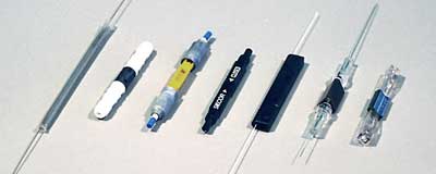
Splices: fusion on the far left, other types of
mechanical splices.
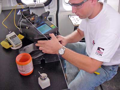
Tech splicing
in a clean, controlled environment splicing trailer
Fusion
Splices
Fusion plices
are made by "welding" the two fibers together usually
by an electric arc. To be safe, you should not do that
in an enclosed space like a manhole or an explosive
atmosphere, and the equipment is too bulky for most
aerial applications, so fusion splicing is usually
done above ground in a truck or trailer set up for the
purpose. (photo above) Splicing on poles is
obviously dangerous too. Its easier to bring extra
cable length into a trailer on the ground and work in
a clean environment for splicing, placing splices in a
closure and testing. The final closure is then placed
in location and the extra fiber carefully looped and
mounted in an appropriate place.
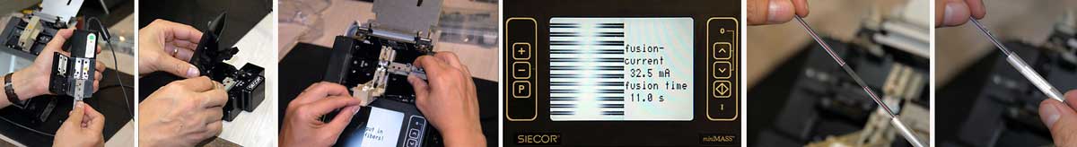
Today's singlemode fusion splicers are automated and
you have a hard time making a bad splice as long as
you cleave the fiber properly. The biggest application
is singlemode fibers in outside plant installations.
Fusion splices are so good today that splice points
may not be detectable in OTDR traces. Some splicing
machines can do one fiber at a time but Mass
Fusion Splicers can do all 12 fibers in a ribbon at
once. Fusion splicers cost $15,000 to $40,000, but the
splices only cost a few dollars each.
The Fusion
Splicing Process
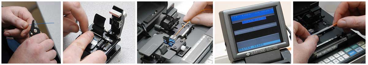
Preparing the Fibers
The fusion splicing process is basically the same for
all automatic splicing machines. The first step is to
strip, clean & cleave the fibers to be spliced.
Strip the primary buffer coating to expose the proper
length of bare fiber. Clean the fiber with appropriate
wipes. Cleave the fiber using the directions
appropriate to the cleaver being used. Place each
fiber into the guides in the fusion splicing machine
and clamp it in place.
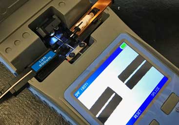
Running the splicer program
First choose the proper program for the fiber types
being spliced. The splicer will show the fibers being
spliced on a video screen. Fiber ends will be
inspected for proper cleaves and bad ones will be
rejected. That fiber must be cleaved again. The fibers
will be moved into position, prefused to remove any
dirt on the fiber ends and preheat the fibers for
splicing. The fibers will be aligned using the core
alignment method used on that splicer. Then the fibers
will be fused by an automatic arc cycle that heats
them in an electric arc and feeds the fibers together
at a controlled rate.
When fusion is completed, the splicing machine will
inspect the splice and estimate the optical loss of
the splice. It will tell the operator if a splice
needs to be remade. The operator removes the fibers
from the guides and attach a permanent splice
protector by heat-shrinking or clamping clam shell
protectors.
Mass (Ribbon) Fusion Splicing
Ribbon cables are fusion spliced one ribbon at a time,
rather than one fiber at a time. Thus each ribbon is
stripped, cleaved and spliced as a unit. Special tools
are needed to strip the fiber ribbon, usually heating
it first, then cleave all fibers at once. Many tools
place the ribbon in a carrier that supports and aligns
it through stripping, cleaving and splicing. Consult
both cable and splicer manufacturers to ensure you
have the proper directions.
More
on fusion splicing.
Video on
fusion splicing on the FOA Channel on 
Mechanical
Splicing
Mechanical
splices are alignment fixtures that hold the ends of
two fibers together with some index matching gel or
glue between them. There are a number of types of
mechanical splices, like little glass tubes or
V-shaped metal clamps. The tools to make mechanical
splices are cheap, but the splices themselves are more
expensive. Many mechanical splices are used for
restoration, but they can work well with both
singlemode and multimode fiber, with practice - and
using a quality cleaver such as those used for fusion
splicing.
Mechanical Splicing Process
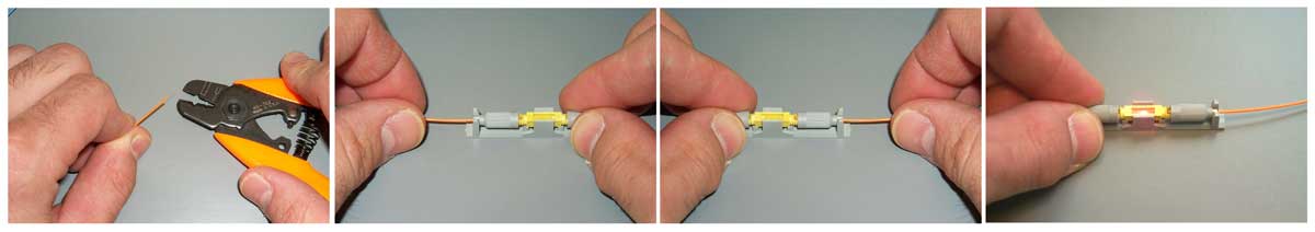
Preparing the Fibers
The splicing process is basically the same for all
types of mechanical splices. The first step is to
strip, clean & cleave the fibers to be spliced.
Strip the primary buffer coating to expose the proper
length of bare fiber. Clean the fiber with appropriate
wipes. Cleave the fiber using the directions
appropriate to the cleaver being used. Using a high
quality cleaver such as those provided with fusion
splicers will yield more consistent and lower loss
splices.
Making The Mechanical Splice
Insert the first fiber into the mechanical splice.
Most splices are designed to limit the depth of the
fiber insertion by the stripped length of buffer
coating on the fiber. Clamp the fiber in place if
fibers are held separately. Some splices clamp both
fibers at once. Repeat these steps for the second
fiber.
You can optimize the loss of a mechanical splice
visually using a visual fault locator, a visible laser
test source if the fiber ends being spliced are
visible. Gently withdraw one of the fibers a slight
amount, rotating it slightly and reinserting it until
the visible light is minimized, indicating lowest
loss.
More
on mechanical splicing.
Video on
mechanical splicing on the FOA Channel on
Color Codes for Splicing
Individual fibers and buffer tubes in loose tube
cables are color coded for identification. When
splicing similar cables on long runs, fibers should be
spliced straight through according to color codes to
continue the same color coding for each joined fiber
in the concatenated cables. When connecting large
fiber count cables to several smaller cables, fibers
should be spliced in order and records kept of the
connections made.
Protecting
Splices
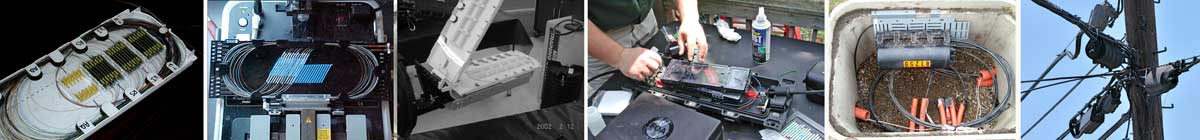
For protection against the outside plant environment and
damage, splices require placement in a protective case.
They are generally placed in a splice tray which is then
placed inside a splice closure for OSP installations or
a patch panel box for premises applications. Indoors,
splice trays are often integrated into patch panels to
provide for connections to the fibers.
There are probably thousands of different types and
options on splice closures. Some are designed for
concatenation of long distance cables where two
identical cables are spliced together. Some closures are
designed for connecting several smaller cables to a
larger one for breaking out the larger cable to several
destinations. Closures can be used for midspan entry
also, where the cable jacket is stripped but most of the
buffer tubes are coiled inside without opening, while
one or more tubes will be opened and spliced to other
cables. Some have cables entering into one end, some
have cable entries on both ends.
There are splice closures designed to be buried, mounted
on walls, hung from cables or poles. Some are small
pedestals themselves. Each type has a particular
application and probably every application has a special
closure. Even special hardware may be necessary for
handling different cable or splice types, so make
certain you have the right hardware before using the
closure. It is recommended that you work with vendors to
find the best closure for your applications then follow
their instructions.
Preparing cables for splice closures involves several
steps that should be followed in the exact sequence
specified by the manufacturer to ensure the cables are
properly secured and the closure will seal. For every
splice closure, it is important to follow the
manufacturers instructions on stripping the cable to
ensure proper lengths of strength members to secure the
cable to the closure and proper lengths of buffer tubes
to connect to the splice trays. The proper length of
fiber is needed to allow splicing and then neatly
storing fiber in the splice tray. Inside splice closures
and at each end, cables with metallic shielding or
strength members must be properly grounded and bonded.
Care should be taken when arranging fibers and splices
in splice trays and buffer tubes in the splice closure
to prevent stress on the fibers. Arranging fibers inside
splice trays may require twisting the fiber but
following the closure manufacturers instructions will
minimize the stress on the fiber. Often the fibers are
broken as the trays and closure are assembled or
re-entered for troubleshooting and repair. Cables must
be secured to the splice closure and sealed properly.
Generally loose tube cables will have the tubes
extending from the entrance of the closure to the tray,
where they are secured, then approximately 1 meter of
bare fibers are organized in the tray after splicing.
Care must be taken to properly bond electrical
conductors such as the armor on some cables or center
metallic strength members to the closure and at each
end.
All closures must be sealed to prevent moisture entry.
Closures must be properly secured, with the location
being determined by the installation type, and excess
cable properly coiled and stored. This may be in a
pedestal or vault, on a pole or tower or buried
underground.
Which Splice
?
If cost is
the issue, fusion requires expensive equipment and but
makes cheap splices, while mechanical splices require
inexpensive equipment and expensive splice hardware.
So if you make a lot of splices (like thousands in an
big telco or CATV network) use fusion splices. If you
need just a few, use mechanical splices.
Fusion splices give very low back reflections and are
preferred for singlemode high speed digital or CATV
networks. However, they may not work well some
multimode fibers, so mechanical splices may be
preferred for MM, unless it is an underwater or aerial
application, where the greater reliability of the
fusion splice is preferred.
Making Good
Splices
Making
consistently low loss splices depends on proper
techniques and keeping equipment in good shape.
Cleanliness is a big issue, of course. Fiber strippers
should be kept clean and in good condition and be
replaced when nicked or worn. Cleavers are most
important, as the secret to good splices - either
fusion or mechanical - is having good cleaves on both
fibers. Keep cleavers clean and have the scribing
blades aligned and replaced regularly. Fusion splicers
should be properly maintained and fusing parameters
set for the fibers being spliced. For mechanical
splices, light pressure on the fiber to keep the ends
together while crimping is important. Use a visual
fault locator (VFL)
to optimize the splice before crimping if possible.
Verifying
Splice Loss
Splices are
permanent joints that cannot be accessed for
individual insertion loss testing with a source and
power meter as connectors are tested. Fusion splicers
generally provide an estimate of connector loss based
on an analysis of data from the alignment system used
by the splicer, but it is only an estimate. An
insertion loss test of the entire finished cable will
be done when installation is finished, but that only
allows comparison to the overall loss predicted by the
loss budget created during the design phase, not
verification of any individual splice.
For concatenations of cables, only an OTDR can see the
splice and confirm its loss, but for accurate loss
measurements it requires testing from both ends and
averaging (see Chapter 8 on Testing.) The OTDR test
will also confirm that the splice is not reflective,
an important issue in many systems. The limited
resolution of the OTDR means that it cannot be used to
verify the splices used to terminate fibers with
pigtails, but a visual fault locator can be used to
check these splices near the ends of the cable.
More
on splices, including hands-on tutorials
Connectors
Most fiber optic connectors are plugs or so-called male
connectors with a protruding ferrule that holds the
fibers and aligns two fibers for mating. They use a
mating adapter to mate the two connectors that fits the
securing mechanism of the connectors (bayonet, screw-on
or snap-in.) The ferrule design is also useful as it can
be used to connect directly to active devices like LEDs,
VCSELs and detectors.
Different connectors and termination procedures are used
for singlemode and multimode connectors. Multimode
fibers are relatively easy to terminate, so field
termination is generally done by installing connectors
directly on tight buffered fibers using the procedures
outlined below. Most field singlemode terminations
are made by splicing a factory-made pigtail onto the
installed cable rather than terminating the fiber
directly as is commonly done with multimode fiber.
Singlemode terminations require extreme care in
assembly, especially polishing, to get good performance
(low loss and reflectance), so they are usually done in
a clean manufacturing facility using heat-cured epoxy
and machine polishing.
Choosing a connector type for any installation should
consider if the connector is compatible with the systems
planned to utilize the fiber optic cable plant, if the
termination process is familiar to the installer and if
the connector is acceptable to the customer. If the
systems are not yet specified, hybrid patchcords with
different connectors on each end may be necessary. If
the installer is not familiar with connector
installation, training may be necessary. And sometimes,
the user may have been sold on a connector type that is
not ideal for the installation, so the installer should
discuss the merits of other types before committing to
the project.
The
Importance of Cleaning Connectors
It is very
important to inspect and clean all fiber optic
connectors properly before testing, including the
connectors on all reference test cables. The core of an
optical fiber is quite small; so small that airborne
dust is often as large as the core of singlemode fiber
and even large compared to multimode fiber. A small dust
particle on a connector ferrule can cause significant
loss and reflectance when two connectors are mated or
contaminate fiber optic transceivers. Dirt can sometimes
even damage the fibers. Liquids like oils on your
fingers can contaminate connectors and make cleaning
difficult.
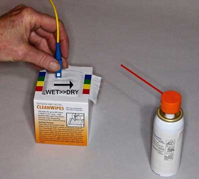
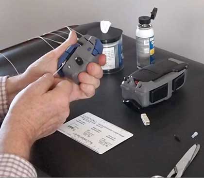
Cleaning fiber optic connectors using a "wet-to-dry"
method is most effective
Cleaning connectors has historically been done with pure
isopropyl alcohol (99% pure) and lint-free wipes in a
wet/dry method. Wet a wipe in a spot with alcohol and
wipe the connector ferrule end across the wet spot then
dry it on the dry wipe. However, today there are many
fiber optic cleaning products available that work better
and are easier to use. There are dry cleaning methods as
well as wet/dry methods, cleaning fluids that are more
effective than alcohol and more effective wipes.
Every test tech should have a fiber optic cleaning kit
and use it to clean all connectors using a
inspect/clean/inspect process to insure the connectors
are properly cleaned.
Styles of
Fiber Optic Connectors
 Since
fiber optic technology was introduced in the late 70s,
numerous connector styles have been developed -
probably over 100 designs. Each new design was meant
to offer better performance (less light loss and
reflectance) and easier, faster and/or more
inexpensive termination. Since
fiber optic technology was introduced in the late 70s,
numerous connector styles have been developed -
probably over 100 designs. Each new design was meant
to offer better performance (less light loss and
reflectance) and easier, faster and/or more
inexpensive termination.
Of course,
the marketplace eventually determines which
connectors are successful. However several attempts to
standardize connectors have been attempted. Some were
unique to systems or networks. FDDI, the first fiber
LAN, and ESCON, the IBM mainframe peripheral
network, required unique connectors. TIA 568
originally called for SC connectors as a standard, but
when users continued to use more STs than SCs and a
whole new generation of smaller connectors were
introduced, TIA-568B was changed to say that any
connector standardized by a FOCIS
standard document was acceptable.
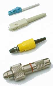
The four
connectors shown at left show how fiber optic
connectors have evolved. The bottom connector is a
Deutsch 1000, the first commercially-available fiber
optic connector. It was really a mechanical splice,
where fibers were held inside the connector with a
tiny screw-tightened chuck. The nose piece was
spring-loaded, allowing exposing the fiber for
cleaving and mating with a small plastic lens in a
mating adapter. The mating adapter also had
index-matching fluid to reduce loss but it was a dirt
problem.
The yellow
connector is an AT&T Biconic. It was developed by
Jack Cook at Bell Labs in the late 1970s. The conical
ferrule was molded from glass-filled plastic. The
first Biconics had ferrules molded around the fiber,
until a die with a tiny 125 micron pin in the exact
center was developed. When Biconics were adapted to
singlemode fiber, the ferrules were ground on a
special grinding machine to center the fiber.
The SC, which
was introduced in the mid-1980s, used a new invention,
the molded ceramic ferrule, that revolutionized fiber
optic termination. Ceramic was an ideal ferrule
material. It could be made cheaply by molding, much
cheaper than machining metal for example. It was
extremely stable with temperature, having similar
expansion characteristics to glass which prevented
"pistoning" when the ferrule came unglued, a problem
with metal or plastic ferrules. It's hardness was
similar to glass which made polishing much
easier. And it readily adhered to fibers
using epoxies or anaerobic adhesives. Today, virtually
all connectors use the ceramic ferrule, usually 2.5 mm
diameter (SC, ST, FC) or 1.25 mm (LC, MU.)
The LC
connector was introduced in the late 1990s to
miniaturize connectors for higher density in patch
panels or equipment. It uses a smaller ceramic
ferrule, 1.25 mm diameter. The LC is the connector of
choice for telecom and high speed data (>1 Gb/s)
networks.
Guide to
Identifying Fiber Optic Connectors
Check out the
"spotters guide" below and you will see the most
common fiber optic connectors. (All the photos are to
the same scale except the MTP, so you can get an idea
of the relative size of these connectors.)
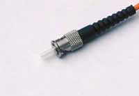
| ST
(an AT&T Trademark) is the one of the most
popular connectors for multimode networks,
like most buildings and campuses. It has a
bayonet mount and a long cylindrical ferrule
to hold the fiber. Most ferrules are ceramic,
but some are metal or plastic. And because
they are spring-loaded, you have to make sure
they are seated properly. If you have high
loss, reconnect them to see if it makes a
difference. |
 |
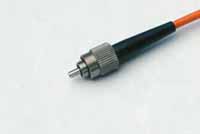
| FC/PC
has been one of the most popular singlemode
connectors for many years. It screws on
firmly, but make sure you have the key aligned
in the slot properly before tightening. It's
being replaced by SCs and LCs. |
 |
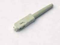
| SC
is a snap-in connector that is widely used in
singlemode systems for it's excellent
performance and multimode systems because it
was the first connector chosen as the standard
connector for TIA-568 (now any connector with
a FOCIS standard is acceptable.) It's a
snap-in connector that latches with a simple
push-pull motion. It is also available in a
duplex configuration. |
 |
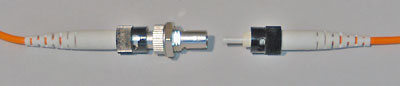
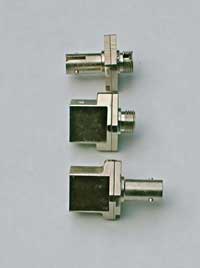
The
ST/SC/FC/FDDI/ESON connectors have the same
ferrule size - 2.5 mm or about 0.1 inch - so
they can be mixed and matched to each other
using hybrid mating adapters. This makes it
convenient to test, since you can have a set
of multimode reference test cables with ST or
SC connectors and adapt to all these
connectors.
From the top:
ST>FC
SC>FC
SC>ST
|
|
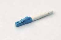
| LC
is a new connector that uses a 1.25 mm
ferrule, half the size of the ST. Otherwise,
it's a standard ceramic ferrule connector,
easily terminated with any adhesive. Good
performance, highly favored for singlemode and
the connector of choice for multimode
transceivers for gigabit speeds and above,
including multimode Ethernet and Fibre
Channel. |
 |
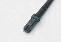
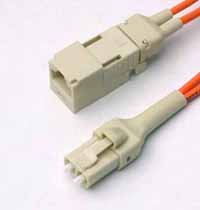
MT-RJ
is a duplex connector with both fibers in a
single polymer ferrule. It uses pins for
alignment and has male and female versions.
Multimode only, field terminated only by
prepolished/splice method. Mostly obsolete.
|
 |
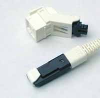
| Opti-Jack
is a neat, rugged duplex connector cleverly
designed around two ST-type ferrules in a
package the size of a RJ-45. It has male and
female (plug and jack) versions. |
 |
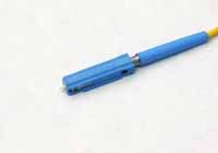
| Volition
is a simple, inexpensive duplex connector that
uses no ferrule at all. It aligns fibers in a
V-groove like a splice. Plug and jack
versions, but one can field terminate jacks
only. |
 |
| MU
looks a miniature SC with a 1.25 mm ferrule.
It's more popular in Japan. |
 |
|
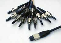
MPO
(sometimes called by the brand name MTP) is
a 12 fiber connector for ribbon cable. It's
main use is for preterminated cable
assemblies.
|
 |
Here
is an even more comprehensive guide to fiber optic
connectors, including obsolete ones.
The
ST/SC/FC/FDDI/ESCON connectors have the same ferrule
size - 2.5 mm or about 0.1 inch diameter- so they can
be mixed and matched to each other using hybrid mating
adapters. This makes it convenient to test, since you
can have a set of multimode reference test cables with
ST connectors and adapt to all these connectors.
Likewise, the LC and MU use the same ferrule (1.25 mm
diameter) so mating is possible.
Connector
Popularity
Two
connectors have become the most popular worldwide, the
SC and LC. The SC is a proven design and many systems
have been built around it already. In premises cabling
there are still many ST in service but new systems tend
to use SCs. LCs are popular with the transceiver
manufacturers since they allow these devices to be made
much smaller and thus systems electronics to have much
higher port density. Internationally there are systems
using MU, E-200 and others but their popularity is lower
than the SC and LC.
The
MPO multifiber connector is used in some high density
prefabricated cabling systems since it can have multiple
rows of 12 or 16 fibers in a single connector. Due to
the difficulty of manufacture, it is not field
terminated. It also has a major drawback, the difficulty
of testing the cables with conventional test equipment.
Specialty
Fiber Optic Connectors
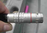 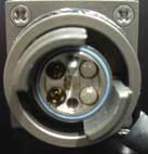
There are a number of specialty fiber optic connectors
available such as this multifiber military connector,
special underwater or aircraft connectors, plastic
optical fiber (POF) connectors, etc. Most have been
designed for very specific applications and require
extremely rigorous qualification testing. Some like the
Mil-C-38999, are copper wiring connectors adapted to
hold fiber optic ferrules. Many of these connectors
require special cable types, termination procedures,
cleaning, handling and test procedures. Refer to
manufacturer's instructions whenever dealing with these
types of connectors.
-
Connector
Ferrule Shapes & Polishes
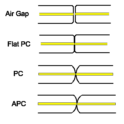
- Fiber
optic connectors can have several different ferrule
shapes or finishes, usually referred to as end
finish or polish types.
- Early
connectors, which did not have keyed ferrules and
could rotate in mating adapters, always had an air
gap between the connectors to prevent them rotating
and grinding scratches into the ends of the fibers.
The ends of the ferrules were polished on hard,flat
surfaces. They are sometimes referred to as NC
or "Non-Fiber Contact" styles.
- Beginning
with the ST and FC which had keyed ferrules, the
connectors were designed to contact tightly, what we
now call physical contact (PC) connectors. These
connectors were still polished flat on the end.
Reducing the air gap reduced the loss and
reflectance (very important to laser-based
singlemode systems ), since light has a loss of
about 5% (~0.25 dB) at each air gap and light is
reflected back up the fiber. While air gap
connectors usually had losses of 0.5 dB or more and
a reflectance of -20 dB, PC connectors had typical
losses of 0.3 dB and a reflectance of -30 to
-40 dB. PC connectors required polishing on a flat
surface with a soft rubber pad to allow the end to
be polished convex.
- Soon
thereafter, it was determined that polishing the
connector ferrules to a convex end face would
produce an even better connection. The convex
ferrule guaranteed the fiber cores were in contact.
Losses were under 0.3dB and reflectance -40 dB or
better.
- The
ultimate solution for singlemode systems extremely
sensitive to reflections, like CATV or high bitrate
telco links, was to angle the end of the ferrule 8
degrees to create what we call an APC or angled PC
connector. Then any reflected light is at an angle
that is absorbed in the cladding of the fiber,
resulting in reflectance of >-60 dB.
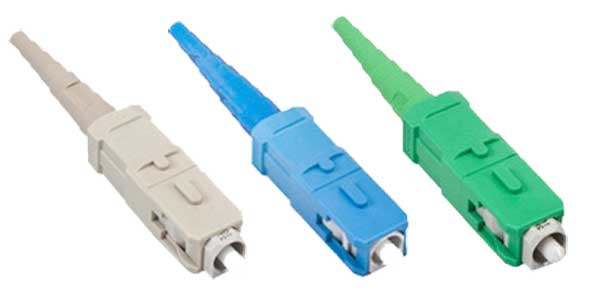
Connector
Color Codes:
Since the
earliest days of fiber optics, orange, black or gray was
multimode and yellow singlemode. However, the advent of
metallic connectors like the FC and ST made color coding
difficult, so colored boots were often used.
The TIA 568 color code for connector bodies and/or boots
has been Beige for multimode fiber, Blue for singlemode
fiber, and Green for APC (angled) connectors. With the
advent of new types of fiber, the choices were widened
as shown in the table below.
Fiber
type
|
Connector
Body
|
Strain
Relief/
Mating Adapter
|
62.5/125
|
Beige
|
Beige
|
50/125
|
Black
|
Black
|
50/125
laser optimized
|
Aqua
|
Aqua
|
Singlemode
|
Blue
|
Blue
|
Singlemode
APC
|
Green
|
Green
|
Termination
Procedures
- Whatever
you do, always follow the manufacturer's termination
instructions closely .
- Multimode
connectors are usually installed in the field on the
cables after pulling, while singlemode connectors
are usually installed by splicing a factory-made
"pigtail" onto the fiber. The tolerances on
singlemode terminations are much tighter than
multimode and the polishing processes are more
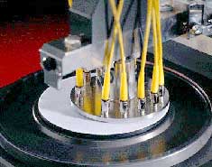
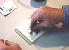
critical, so singlemode termination is better
done in a factory environment using polishing
machines (left, below). You can install singlemode
connectors in the field for low speed data networks,
but you may not be able to get losses lower than 1
dB and reflectance may be a problem! Multimode
connectors are easier to install and polish (below,
right) so are often done in the field by trained
technicians.
- Connectors
can be installed directly on most cable types,
including jacketed tight buffer types like simplex,
zipcord and breakout cables, where the where the
aramid fiber strength members in the cable are
crimped or glued to the connector body to create a
strong connector. Connectors can be attached to the
900 micron buffered fibers in distribution cables,
but the termination is not as rugged as those made
to jacketed cables, so they should be placed in
patch panels or boxes for protection. The 250 micron
buffered fibers in loose tube cables cannot be
easily terminated unless they have a reinforcement
called a breakout kit or furcation kit installed,
where each fiber is covered by a larger plastic
tube. Generally loose tube and ribbon cables are
terminated by splicing on a terminated pigtail.
- Cables can
be pulled with connectors already on them if, and a
big if, you can deal with two issues: First, the
length must be precise. Too short and you have to
pull another longer one (its not cost effective to
splice), too long and you waste money and have to
store the extra cable length. Secondly, the
connectors must be protected. Some cable and
connector manufacturers offer protective sleeves to
cover the connectors, but you must still be much
more careful in pulling cables. You might consider
terminating one end and pulling the unterminated end
to not risk the connectors. There is a growing
movement to install preterminated systems with the
MTP 12 multifiber connector. It's tiny not much
bigger than a ST or SC, but has up to 12 fibers.
Manufacturers sell multifiber cables with MPOs on
them that connect to preterminated patch panels with
STs or SCs. (See "Do You Have To Terminate In
The Field" below.)
Multimode
Terminations: Several different types of terminations
are available for multimode fibers. Each version has
its advantages and disadvantages, so learning more
about how each works helps decide which one to use.
Singlemode
Terminations: Singlemode fiber requires different
connectors and polishing techniques that are best done
in a factory environment. Consequently most SM fiber
is field terminated by splicing on a
factory-terminated pigtail. Singlemode termination
requires special connectors with much tighter
tolerances on the ferrule, especially the hole for the
fiber. Polishing requires special diamond polishing
film on a soft rubber pad and a polishing slurry to
get low reflectance. But you can put SM
connectors on in the field if you know what you are
doing. Expect higher loss and high reflectance.
Termination
Processes
Adhesive/Polish
Terminations
Most connectors use epoxies or other adhesives to hold
the fiber in the connector ferrule and polish the end
of the fiber to a smooth finish. Follow termination
procedures carefully, as they have been developed to
produce the lowest loss and most reliable
terminations. Use only the specified adhesives, as the
fiber to ferrule bond is critical for low loss and
long term reliability! We've seen people use hardware
store epoxies, Crazy Glue, you name it! And they
regretted doing it. Only adhesives approved by
manufacturers or other distributors of connectors
should be used. If the adhesive fails, not unusual
when connector ferrules were made of metal, the fiber
will "piston" - sticking out or pulling back into the
ferrule - causing high loss and potential damage to a
mated connector.
The
polishing process involves three steps which only
takes a minute: "air polishing" to grind down the
protruding fiber, polishing on a soft pad with the
fiber held perpendicular to the polishing surface with
a polishing puck and a quick final fine polish.
Epoxy/Polish:
Most connectors, including virtually all factory made
terminations, are the simple "epoxy/polish" type where
the fiber is glued into the connector with epoxy and
the end polished with special polishing film. These
provide the most reliable connection, lowest losses
(less than 0.5 dB) and lowest costs, especially if you
are doing a lot of connectors. The small bead of
hardened epoxy that surrounds the fiber on the end of
the ferrule even makes the cleaving and polishing
processes much easier - practically foolproof. The
epoxy can be allowed to set overnight or cured in an
inexpensive oven. A "heat gun" should never be used to
try to cure the epoxy faster as the uneven heat may
not cure all the epoxy or may overheat some of it
which will prevent it ever curing. Don't use "Hot
Melt" ovens either, as they use a much higher
temperature and will ruin the epoxy.
"Hot Melt"
Adhesive/Polish: This is a 3M trade name for a
connector that already has the epoxy (actually a heat
set glue) inside the connector. You insert the
connector in a special oven. In a few minutes, the
glue is melted, so you remove the connector, insert
the stripped fiber, let it cool and it is ready to
polish. Fast and easy, low loss, but not as cheap as
the epoxy type, it has become the favorite of lots of
contractors who install relatively small quantities of
connectors. Remember you need a special Hot Melt oven,
as it needs a much higher temperature than is used for
curing epoxy.
Anaerobic
Adhesive/Polish: These connectors use a quick setting
"anaerobic" adhesive to replace the epoxy or Hot Melt
adhesive that cures faster than other types of
adhesives. They work well if your technique is good,
but some do not have the wide temperature range of
epoxies. A lot of installers are using Loctite 648,
with or without the accelerator solution, that is neat
and easy to use.
More
on adhesive/polish connectors.
Videos on
termination on the FOA Channel on
Crimp/Polish:
Rather than glue the fiber in the connector, these
connectors use a crimp on the fiber to hold it in.
Early types offered "iffy" performance, but today they
are pretty good, if you practice a lot. Expect to
trade higher losses for the faster termination speed.
And they are more costly than epoxy polish types. A
good choice if you only install small quantities and
your customer will accept them.
Prepolished/Splice
Connectors And Splice-On Connectors (SOC)
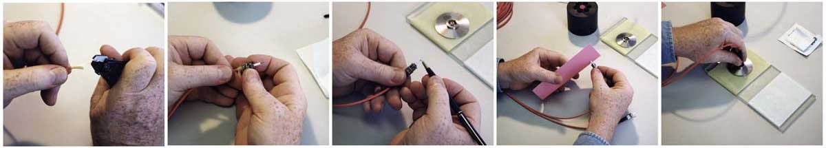
Prepolished/Splice
Connector (Corning Unicam) and Splice-On Connectors (EasySplicer)
Prepolished/splice
and
splice-on connectors eliminate the need for field
adhesives and polishing by terminating connectors to a
stub fiber in a factory and attaching it to the fiber
with a mechanical splice (prepolished/splice
connectors) or a fusion splice (splice-on connectors,
called SOCs). Terminating the fiber them becomes a
splicing process instead of the more complicated
polishing methods. The termination process involves
cleaving the fiber and attaching the connector with a
built-in mechanical splice or using a fusion splicing
machine. It is faster than the adhesive/polish
connectors when done by an experienced tech.
These
connectors
require analysis of the economics of their use. Both
methods require investment in special equipment.
Prepolished/splice connectors generally require
special termination kits for each manufacturer's
connector due to the uniqueness of the connector and
splice. Some kits provide an inexpensive cleaver which
is difficult to use so it should be replaced with a
precision cleaver as used with fusion splicers.
Splice-on connectors require a fusion splicing
machine, more expensive than the kits for prepolished
splice connectors, and some of these connectors only
work with specific manufacturer's splicing machines.
The
connectors themselves are more expensive than a
typical connector used for adhesive/polish
termination. The ones with mechanical splices are
generally much more expensive than the fusion
splice-on connectors. Another factor in cost is the
yield. Fusion splice-on connectors will have lower
loss and virtually 100% yield while mechanical
prepolished/splice connectors will have average
higher losses and lower yield.
A
misconception concerns connectors that are installed
by splicing on the end of a fiber, wither by
mechanical or fusion splicing, or by splicing on a
pigtail. The connection loss of this type of
termination includes the typical connection loss
tested when mated to a reference connector plus the
splice used to attach the connector to the fiber, as
the splice is the attachment method and therefore
included in the connection loss. This is how standards
often list high losses for connectors because they
must include not only the direct attach
adhesive/polish connectors but also splice-on
connectors and array connectors with many fibers.
More
on prepolished/splice connectors.
Read more
about termination processes and view the actual
processes involved in termination with "Virtual
Hands-On" tutorials and on the FOA Channel on .
See the Table of Contents
for listings of termination types under Components.
Hints for
doing field terminations
Here are a
few things to remember when you are terminating
connectors in the field. Following these guidelines
will save you time, money and frustration.
Choose the
connector carefully and clear it with the customer if
it is anything other than an epoxy/polish type. Some
customers have strong opinions on the types or brands
of connectors used in their job. Find out first, not
later!
Never, never,
NEVER take a new connector in the field until you have
installed enough of them in the office that you can
put them on in your sleep. The field is no place to
experiment or learn! It'll cost you big time!
Have the
right tools for the job. Make sure you have the proper
tools and they are in good shape before you head out
for the job. This includes all the termination tools,
cable tools and test equipment. Do you know your test
cables are good? Without that, you will test good
terminations as bad every time. More and more
installers are owning their own tools like auto
mechanics, saying that is the only way to make sure
the tools are properly cared for.
Dust and
dirt are your enemies. It's very hard to terminate or
splice in a dusty place. Try to work in the cleanest
possible location. Use lint-free wipes (not cotton
swaps or rags made from old T-shirts!) to clean every
connector before connecting or testing it. Don't work
under heating vents, as they are blowing dirt down on
you continuously.
Don't
overpolish. Contrary to common sense, too much
polishing is just as bad as too little. The ceramic
ferrule in most of today's connector is much harder
than the glass fiber. Polish too much will cause
undercutting of the fiber and you create a concave
fiber surface not convex as it should be, increasing
the loss. A few swipes is all it takes.
Change
polishing film regularly. Polishing builds up residue
and dirt on the film that can cause problems after too
many connectors and cause poor end finish. Check the
manufacturers' specs.
Put covers
on connectors and patch panels when not in use. Keep
them covered to keep them clean.
Inspect and
test, then document. It is very hard to troubleshoot
cables when you don't know how long they are, where
they go or how they tested originally! So keep good
records, smart users require it and expect to pay
extra for good records.
Prefabricated
Cabling Systems: Do You Have To Terminate In The
Field?
Not
necessarily. Many manufacturers offer prefabricated
fiber optic cabling systems for both premises and
outside plant systems. In fact, the largest
application for prefabricated systems is fiber to
the home (FTTH) where it saves a tremendous amount of
time in installation and cost. Using prefab systems
requires knowing precisely where the cable will be run
so cable lengths can be specified. Using CAD systems
and design drawings, a complete fiber optic cabling
system is designed to the customer's specifications
and built in a factory using standard components.
Early prefabricated systems (some are still
available) simply terminated cables with standard
connectors like STs or SCs and put them inside a
plastic pulling boot with a pulling loop attached to
the fiber strength members. The cable would be placed
with the boot in place then removed to connect into
patch panels.
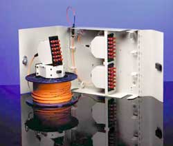
Today, it's
more common to use backbone cables terminated in small
multifiber MPO connectors that are pulled from room to
room and connected to rack-mounted modules that have
MPO connectors on the back and single fiber connectors
on the front (see photo of Fiberware system.) Like
everything else, there are tradeoffs. The
factory-assembled connectors usually have lower loss
than field terminations but the MPO connectors, even
factory assembled, are not low loss, so the total loss
may be more than field terminated systems. Costs also
involve tradeoffs, as factory systems are more
expensive for the components but installation time is
much less.
In new
facilities, considering prefabricated systems is
always a good idea, but all factors should be
considered before making a decision.
More
on prefab cable systems.
More
on connectors and termination, including hands-on
tutorials.
Test
Your Comprehension
Table of Contents: The FOA
Reference Guide To Fiber Optics
|