Guidelines On What Loss To Expect When
Testing Fiber Optic Cables
To be able to judge whether a fiber optic cable plant is good, one does a
insertion loss test with a light source and power meter and compares that
to an estimate of what is a
reasonable loss for that cable plant. The estimate, called a "loss budget"
is calculated using typical component losses for each part of the cable
plant - the fiber, splices and/or connectors. If the measured loss exceed
the calculated loss by a significant amount (remembering the inherent
uncertainty in all measurements), the system should be tested
segment-by-segment to determine the cause of high loss.
A loss budget estimate can also be used to compare results from OTDR
testing, but the inherent uncertainties of OTDR testing make the estimate
less accurate. See OTDR Measurement Uncertainty in the OTDR
page.
Some
standards refer to the loss budget as the "attenuation allowance" but
there seems to be very limited use of that term.
The calculated loss budget is an estimate
that assumes the values of component losses and does not take into
account the uncertainty of the measurement. Be aware of this because
if measurements are close to the loss budget estimates, some judgement
is needed to not fail good fibers and pass bad ones! This is discussed
in depth in the page on "Installation
Deliverables and below"
Cable Plant Loss Budget
The cable plant "loss budget" is a function of the losses of the
components in the cable plant - fiber, connectors and splices, plus any
passive optical components like splitters in PONs.
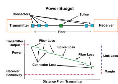
Thus the loss budget of the cable plant is a major factor in the power
budget of the fiber optic link and is what one calculates to compare
against tested insertion loss (and even compares to OTDR loss
measurements) to determine if the cable plant is properly installed.
FOA has a online Loss
Budget Calculator web page that will calculate the loss budget for
your cable plant. This is a good page to bookmark on your smartphone,
tablet and/or laptop to have for making calculations in the field.

FOA also has a free app for iOS smartphones and tablets that will
calculate loss budgets for the cable plant you are designing or testing.
See the Apple app store for your device for details.
Calculating
Loss Budgets
Calculating a loss
budget for a cable plant involves estimating all the component losses -
fiber, splices and connectors - and summing them up.
- Go
here for more comprehensive discussion on how to calculate a loss
budget.
-
- Connector
Loss
- For each
connector, we usually figure 0.3 dB loss for most adhesive/polish or
fusion splice-on connectors. The loss spec for prepolished/mechanical
splice connectors or multifiber connectors like MPOs will be higher
(0.75 max per EIA/TIA 568)
- When testing
cable plants per OFSTP-14 (double ended), include connnectors on both
ends of the cable when using the 1-cable reference For other options
see the note below. When testing per FOTP-171 (single ended), include
only one connector - the one attached to the launch cable.
-
- Splice
Loss
- For each
splice, figure 0.3 dB for multimode mechanical splices (0.3 max per EIA/TIA
568) and 0.15dB for singlemode fusion splices.
-
- Fiber
Loss
- For multimode
fiber, the loss is about 3 dB per km for 850 nm sources, 1 dB per km
for 1300 nm. (3.5 and 1.5 dB/km max per EIA/TIA
568) This roughly translates into a loss of 0.1 dB per 100 feet
(30 m) for 850 nm, 0.1 dB per 300 feet(100 m) for 1300 nm.
- For singlemode
fiber, the loss is about 0.5 dB per km for 1310 nm sources, 0.4 dB per
km for 1550 nm. (1.0 dB/km for premises/0.5 dB/km at either wavelength
for outside plant max per EIA/TIA 568)This
roughly translates into a loss of 0.1 dB per 600 (200m) feet for 1310
nm, 0.1 dB per 750 feet (250m) for 1300 nm.
-
- So
for the estimated loss of a cable plant, calculate the approximate
loss as:
-
- (0.5 dB X #
connectors) + (0.2 dB X# splices) + (fiber attenuation X the total
length of cable)
-
- For more
information see calculate a loss budget.
-
- What
about OTDR testing?
- OTDRs are used
for verifying individual events like splice loss on long links with
inline splices or for troubleshooting. All standards require an
insertion loss test for qualification of the link loss. In MM fibers,
the OTDR will underestimate the loss considerably - as much as 3 dB in
a 10 dB link - but the amount is unpredictable. In long distance SM
links, the difference may be less, but there are other measurement
uncertainties, like connector or splice loss, where the OTDR can show
a gain.
- What happens
when you test with an OTDR with its limited distance resolution?
Specifically, if you have singlemode fiber terminated with fusion
spliced pigtials, you cannot see the both splice and the connector
losses. Or what if you have a patch panel with connections using short
patchcords?
For insertion loss testing, you simply sum up all the loss
contributors and get a total for the cable run. In the case of an
OTDR, you are analyzing each event.
So if you have a connection point where both fibers were terminated
with spliced-on pigtails, you should analyze the event as the sum of 2
fusion splices and one connection, not each individually. A patchcord
termination would be two connection losses, plus splices if the
termination was by splicing on pigtails.
- For more on
OTDRs, see the
FOA Online Reference Guide on Testing or Lennie
Lightwave's Guide.
- Note
On Including Connectors On The Ends And Test Methods
- Many designers
and technicians wonder when doing a loss budget whether the connectors
on the end of the cable plant should be included in the loss budget.
The answer is yes, they should be included for two reasons:
- 1) When the
cable plant is connected up to communications equipment with
patchcords, the connections to the patchcords will have loss.
- 2) When the
cable plant is tested, the reference cables will mate with those
connectors on the ends and their loss will be included in the
measurements but the results depends on the
method used to set the "0dB"
reference.
Testing standards
often include 3 different ways of setting the "0dB" reference for
testing loss.
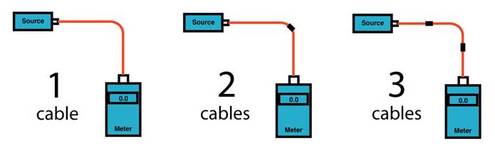
- All three of
these methods are approved in many standards, but it is important to
realize they will give different loss readings due to
the connections included when making the 0dB reference measurement. The
math of these methods is discussed in detail here.
1 cable reference) If the "0dB" reference for the insertion
loss test was done with only 1 reference test cable attached between
the light source and power meter (which is the most common way,) the
connectors on both ends of the cable will be included in the loss so
the loss budget should include both connectors.
3
cable reference) If the "0dB" reference for the
insertion loss test was done with three cables, the launch reference
cable, a receive reference cable and a third reference cable between
them, a method used for many plug and jack (male/female) connectors
such as MPOs, the loss budget should not incude the connectors on the
end. When making the "0dB" reference with three cables, two
connections are included in setting the reference so the measured
value will be reduced by the value of those two connections. If the
loss budget is calculated without the connectors on the ends, the
value will more closely approximate the test results with a 3-cable
reference.
2
cable reference) While the two-cable reference
method is rarely used, it includes only one connector. Thus you could
use the same approach when calculating loss budgets for this test
method.
Whatever test method is presumed, it must be documented when the loss
budget is calculated.
- Will
the network run on that link?
- Here is a table
showing the loss margin for most fiber optic LANs and links. If
the loss of the cable plant is less than the maximum loss allowed for
the link, it should run (but you really want a little bit of margin!)
Evaluating
Cable Plant Test Data Compared To The Link Loss Budget
To prove the cable plant was installed properly requires test data, of
course. During the design phase, loss
budgets calculated for each cable run should provide an estimate
of the expected loss of the fibers in each cable link to compare to
actual test results.
Short fiber optic
premises cabling networks are generally
tested in three ways, connector
inspection/cleaning with a microscope, insertion
loss testing with a light source and power meter or optical loss
test set, and polarity data, meaning that the routing of fibers is
confirmed so that when connecting equipment the tech can identify fiber
pairs for transmit and receive. Polarity testing generally can be done
with a visual fault locator to confirm that fibers are connected per the
documented cable diagrams.
Outside plant (OSP) testing is more complex. If the cable plant includes
cables concatenated with splices, it's expected to add OTDR
testing to the connector inspection, insertion loss and polarity
testing. If the link has passive devices like FTTH splitters or WDMs,
those need to be tested and documented also.
There is one thing that whoever is reviewing the data - and going back
to the design phase, whoever writes the test specifications based on the
loss budgets in the first place - needs to understand: none of
these are absolute numbers. The loss budget which is
created early in the design phase estimates the loss of
the cable plant based on estimates of component loss and
therefore is not an absolute number, but an estimate to
be used to compare to test data.
Test data is created by instruments and related components that make
measurements which have measurement errors. There
are always factors in making measurements that cause the instrument
reading to be inaccurate - only an approximation of the real value
- and the real value is unknowable because of measurement errors. (If
you are curious, look up the Heisenberg uncertainty principle.)
Let's
look at this symbolically:
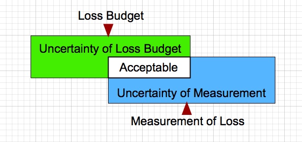
The loss budget is not exact, nor is the testing, so there is a
range of measurements that should be acceptable. Some judgement
is needed to determine if a particular fiber's test results are
acceptable. In our experience,
those two factors cause more stress between managers and installers than
just about any other factor in a cable
plant project. Consider these examples of the issues with loss budgets
and testing errors.
Example:The
loss budget for each fiber in a cable plant link is 8.0 dB but the
measured loss with a light source and power meter is 8.2dB. Should that
fiber be rejected? Well, no, because the uncertainty of the loss budget
is probably ~+/-0.5dB, providing a range of 7.5 to 8.5dB loss. The
uncertainty of the loss test is probably in the same range, so the
actual loss is in the range of 7.7 to 8.7dB. Thus there is considerable
overlap of the loss budget and the measurement results, so there is no
reason to reject this fiber. However if one fiber is testing at over
9dB, there is reason to double check tests to determine if it is
acceptable. All this requires considerable judgement.
(C) 2004-20 The Fiber
Optic Association, Inc.
More detailed information can be found on the FOA
Online Reference Guide.
Return To The FOA Home Page
Return To FOA Tech Topics