
| Testing
Bare Fiber There are two reasons we may want to test bare fiber, by that we mean fiber that has not been terminated in connectors but is simply plain optical fiber, The first one is to ensure the fiber or cable being manufactured meets its specifications, as is done by every manufacturer. The second reason is to test cable on the reel to ensure it is in good condition before we install it (or even purchase it or accept it when delivered.) Manufacturing Testing Fiber Or Cable Manufacturing testing requires more precise measurements as the specifications of the fiber and/or cable are guaranteed by the manufacturer. The most accurate way of measuring the fiber attenuation coefficient requires transmitting light of a known wavelength through the fiber and measuring the changes over distance. The conventional method, known as the cutback method, involves coupling fiber to the source and measuring the power out of the far end. The fiber is then cut near the source and power measured again. For more accurate measurements, use mode conditioning on the fiber near the source. Multimode fiber needs careful conditioning with a mandrel wrap or other mode conditioner while singlemode fiber just needs one small loop (~2 inches or 50mm) to ensure the fiber is transmitting only one mode. 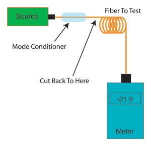 By knowing the power at the source and end of the fiber and the length of the fiber, its attenuation coefficient can be determined by calculating:  An alternative method of testing fiber, which may be easier in field measurements, involves using a fiber pigtail attached to the source for a launch cable. Then use a temporary fusion or mechanical splice on the other end to connect to the fiber to be tested. (If using a fusion splice, it's not necessary to use a splice protector since the splice is temporary.) This is similar to the single-ended loss measurement of terminated cables, but uses a splice instead of connectors at the source end and a bare fiber adapter to connect the fiber to the power meter. This method introduces more uncertainty in the measurement because of the loss of the splice coupled to the fiber under test, since it may not be easy to accurately calibrate the output power of the pigtail. The best method is to use a bare fiber adapter on the power meter to measure the output of the bare fiber, then attach the splice. Alternately, have the splice attached on the pigtail and couple a fiber to the pigtail with the splice and measure the power. Remember that the splice requires a good cleave to get reliable measurements so a good fusion splicer cleaver is recommended. Also it may be necessary to renew the index-matching gel in the splice occasionally or replace the splice if it gets contaminated. 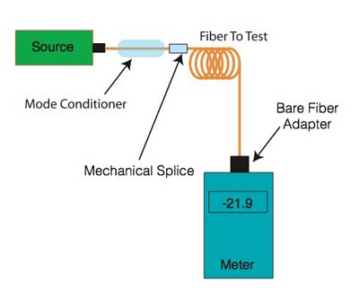 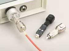 Bare fiber adapters The third method of testing fiber attenuation is to use an OTDR, assuming the fiber is long enough for it to be seen in an OTDR trace (typically >~50m). The OTDR uses an indirect method of measuring loss that involves the backscatter from the fiber. Cables can be attached to the OTDR with a launch cable with a mechanical splice to connect to the fiber under test. 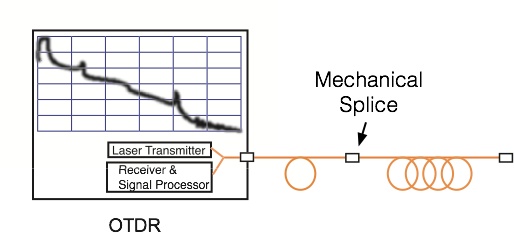 Bare fiber is usually tested with a launch cable with a connector on the OTDR end and bare fiber on the test end, with the bare fiber to be tested connected to the launch cable with a temporary fusion or mechanical splice. (If using a fusion splice, it's not necessary to use a splice protector since the splice is temporary.) One needs only take a trace of the fiber and use the loss between two markers a known distance apart to calculate the loss coefficient of the fiber. 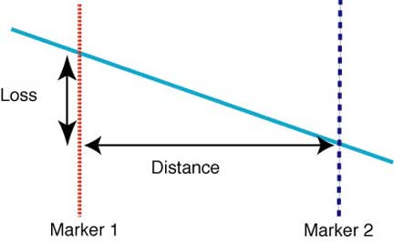 OTDRs generally offer two methods of making this measurement, a simple "two point" method shown here or the "least squares" method which calculates the best fit between the two markers, reducing the effects of noise on the measurement. Either method should measure the loss of the fiber by placing the markers just after the spice to the launch cable and just before the end of the fiber, avoiding the tail of the splice event and the noise at the end of the fiber. Using least squares testing will minimize the effects at the ends of the fiber. Recommended Reading: Optical Fiber Testing Loss testing Accuracy. More information on mode conditioning for multimode fibers and measurement methods including encircled flux. Field Testing Fiber Or Cable Often, it is necessary to test a spool of cable prior to installation to ensure it has not been damaged. This may involve either a quick continuity check or measurement of the actual loss. If the fiber is new and just delivered to the work site, a continuity check may be all that is necessary. If the fiber is old or suspected of damage, an actual loss test as described above may be necessary. Continuity Testing Often continuity testing is considered adequate, especially if you want to ensure that a cable was not damaged in transit. Obviously, visual inspection of the cable on the reel should be done first to detect any signs of damage. For visual testing, simply use a high-power visible laser visual fault locator (VFL) with a pigtail and mechanical splice as shown above for loss testing. As with any splice, a good fiber cleave is needed to ensure good fiber coupling. You should cleave both ends since it will make it easier to see the visible light at the far end. The coupling of bare fiber to a VFL with a mechanical splice is simple as you can actually see the light lost in the splice. 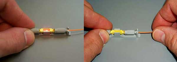 If the fiber to be tested is multimode and relatively short, a LED fiber tracer can be used with a bare fiber adapter. It is unlikely that a broken or cut fiber will couple much power, so a good cleave is needed also. If using a VFL, the maximum distance that one can check for continuity is ~5km and with a visual trace in multimode fiber, perhaps ~500m to 1km. More on visual continuity testing. If the fiber is too long for visual continuity testing, a quick cutback or OTDR test may be a better choice. See the description above. |
|
|