
| Topic: Singlemode Fiber Temination | Table of Contents: The FOA Reference Guide To Fiber Optics |
| Singlemode
Fiber Termination and Polishing Because the core diameter of singlemode fiber is only 9 microns compared to the 50-62.5 micron diameter of multimode fiber, minute scratches and alignment become much more critical in singlemode connectors. Connectors with closer mechanical tolerances are used to minimize the difference between the ferrule hole and the fiber diameter to reduce fiber eccentricity in the ferrule and minimize offset contributions to loss. In singlemode applications, there is usually also concern over relectance (also called return loss or back reflection.) Since reflectance and loss are a concern, the polishing technique must be changed from that used with multimode connectors. The difficulty of getting high quality SM terminations in the field is the reason most SM installations are terminated by fusion splicing pigtails onto the fibers in the installed cables. Polishing singlemode connectors is generally done using automated polishers that provide proper end surface geometry, but hand polishing can be done if proper procedures are followed. Generally, SM terminations are done using an epoxy/polish process as the small epoxy bead on the end of the connector helps in the polishing processes. The fiber is cleaved and air-polished as with a MM connector. 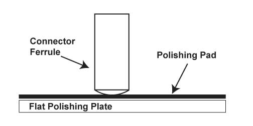 A rubber pad (3mm, 80 durometer hardness) is always used on a flat polishing surface to present a soft surface to the connector. This helps polish the ferrule in a convex-shape and provide a physical contact (PC) connection when mated with another connector. Some users prefer plastic or nylon polishing pucks while others prefer hard stainless steel, so either are considered acceptable. The connector is generally "wet" polished on a diamond grit lapping films. Alcohol or a polishing "slurry" acts as a coolant, lubricant and also helps keep the lapping film clean. Diamond grit used instead of aluminum oxide lapping film to get a more even polish. When using the aluminum oxide paper the fiber is polished away at a faster rate than the ferrule. This can actually leave the fiber recessed in the ferrule. The diamond grit will polish away ferrule material along with the glass fiber to leave a clean, convex, physical-contact connector. The same deburring method is used as in multimode polishing, air polish with 12 micron aluminum oxide polishing film. After deburring, the connector is placed in a plastic/nylon polishing puck or a stainless steel puck. The diamond grit will grind stainless steel away shortening the life of the polishing film. For highest surface finish, it is sometimes recommended that a nylon puck be dedicated to each grade of polishing film. The connector is polished in a "figure O" pattern. The "figure O" will give a more thorough polish and help give the connector the proper convex shape. Inspecting Singlemode Connectors Singlemode connectors can be inspected by a normal microscope at higher magnification (200-400X) for scratches, cracks, etc. (More on microscope inspection.) Interferometry testing is used in singlemode termination to measure the three key physical endface parameters of a PC polished connector. Radius of Curvature 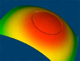 Connector endface profile by interferometry
Interferometers are powerful tools for inspecting SM connectors but are lab, not field instruments and are expensive, limiting their use to manufacturing facilities. Singlemode Termination Process: Cable Preparation and Connector Attachment Use only singlemode connectors and the manufacturer-recommended epoxy and polishing films. Follow the directions for the connectors and adhesive (epoxy or anaerobic) being used for the termination. These processes are exactly the same as multimode fiber. Step-by-Step Polishing For Low Loss and Back Reflection Singlemode polishing is normally done with an "air polish" to remove the fiber left after cleaving, a first polish on 5 micron diamond film and a final polish on 1 micron diamond film. This should yield -30 dB back reflection (30 dB return loss. If better back reflection performance is needed, a final polish with 0.3 micron diamond film is used. To achieve the scratch-free polished needed for a low return loss and low insertion loss singlemode connector, follow these directions.
|
|
|