Optical LANs (OLANs) or Fiber Optic Local Area Networks (LANs)
Introduction
Centralized Cabling - Fiber to the Desk and Fiber To The Office
Passive Optical LANs
Designing And Installing Optical LANs (OLANs)
Testing OLANs
Introduction
Optical LANs have been around since the mid-1980s but in the last few years they have benefited from the worldwide move to install fiber to the home. With over 100 million FTTH subscribers, FTTH has become a market driven by the economies of scale and costs have plummeted. It did not take long for designers to understand that FTTH, especially as used in multi-dwelling units, was similar to typical LANs. Much as LANs based on telco PBX architectures became the first standard for LANs, telco FTTH architectures, especially PONs (passive optical networks), are being adopted for the next generation of LANs. Here you will find some history and an explanation of how this new generation of telco architecture is being widely adopted.
Background Information
Additional links to FOA Guide pages are provided in the text.
The Development of LANs and Premises Cabling
Networks that allowed computers to communicate with other computers and peripherals have been around for a long time. They evolved in two directions - wide area networks using phone lines and then the Internet, and local area networks (LANs) where most connected devices were in a building or campus. Networking PCs began seriously in the mid 1980s with many competing networks, most proprietary: Ethernet, IBM Token Ring, DECnet, WangNet, etc. mostly using higher bandwidth coax cable or shielded twisted pair. Over time, Ethernet, developed by Xerox Palo Alto Research Labs, became the most popular. AT&T recognized the need for computer networks and created StarLAN using telephone wire. Not long afterwards, two people left Xerox PARC and started Synoptics, originally to do LANs over fiber but they discovered balanced transmission and created LattisNet which was close to what became 10BASE-T.
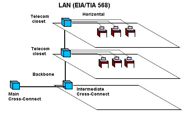
Local area networks (LANs) used to connect computers in a premises (indoor building) environment have been mostly based on standardized structured cabling. Structured cabling standards were developed around 1990 based on a 1982 AT&T survey of a small number of users of phone private switches (PBXs or private branch exchanges) that showed that most users were less than 300 feet (about 100m) from the switch. Using this information, a structured cabling architecture based on backbone cabling to local telecom rooms containing LAN hubs or switches that served users over copper cables was adopted. Early additions to the standard allowed for longer backbone distances using optical fiber.
Here is a diagram of early structured cabling, appropriately using a graphic from the era. Note the use of telecom nomenclature.
Over time, Ethernet network speeds grew from 10 to 100MB/s and then 1Gb/s. Fiber was quickly recognized as a simpler way to upgrade to higher speeds and provide longer backbone connections. Both multimode and singlemode fiber were added to the cabling standards for backbones with longer lengths and multimode was added to the horizontal link but still with the same 100m length limit.
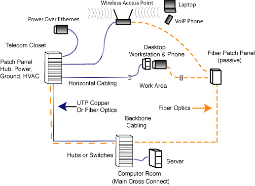
The additional link length capability of fiber was later recognized by allowing a "centralized fiber" architecture in the standards. Here fiber connects the desktop directly without the electronics in the telecom closet (renamed telecom room in later versions of the standard.) Since fiber needs no intermediate electronics, the cost of equipment drops and the need for power, AC and grounds - or even the space allocated for the equipment (the telecom room) - means the cost of equipping telecom rooms goes away, easily offsetting the higher cost of the fiber electronics needed to interface to the connected device. The cost of the fiber cabling, meanwhile, had dropped and copper increased, so the cabling cost itself was often less for fiber than copper.
Meanwhile, wireless (WiFi) had become more capable of handling typical network traffic and users had begun migrating from desktop computers to laptops, tablets and smartphones using wireless, so architectures to support WiFi were being used in addition to desktop cabling.
Here is the current day architecture of centralized fiber compared to normal structured cabling and the addition of WiFi access points.
The Bandwidth Issue
To keep up with the needs to transfer more and more data, Ethernet advanced to higher speeds. 1 - 10 -100Mb/s came quickly and with little pain, although users had to upgrade numerous times from Cat 3 - 4 - 5 -5e - 6A) at very high expense. But 1Gb/s and 10Gb/s stressed the unshielded twisted pair cable preferred by most users. Transceivers had to become more sophisticated, power hungry and cabling needed more bandwidth.
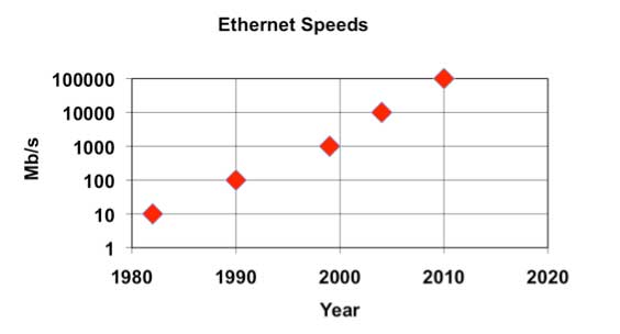
Ethernet Speed Development
Cat 5, practically the only cable needed in the 1990s, was almost OK for 1Gb/s Ethernet using new types of transceivers, but a small upgrade to "enhanced" Cat 5 or Cat 5e made it good for another few years. Cat 6, yet higher bandwidth UTP, never had a network that called for it and it was inadequate for 10Gb/s Ethernet, which led to the development of Cat 6A (augmented Cat 6).
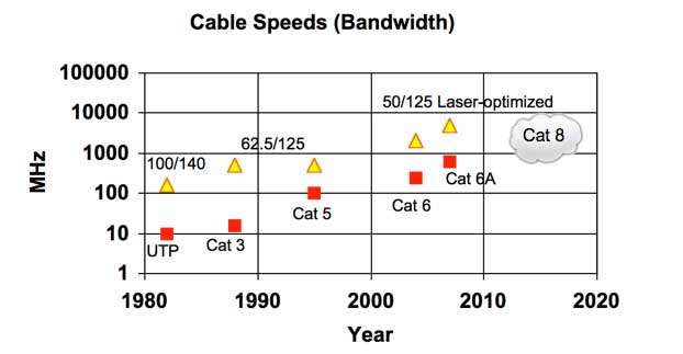
Cabling Speed Development For UTP And Multimode Fiber Cables
The speed upgrade to Ethernet at 10Gb/s created a new set of problems. UTP copper cabling, the basic cabling of structured cabling, required continual upgrades to meet the needs of faster networks. As speeds exceeded 1Gb/s, copper development was much slower than fiber and links required much higher power to support the higher bandwidth signals. Proposals to develop a new cable -Cat 8 - for higher speed networks like 40G Ethernet over short distances are being evaluated.
Multimode fiber also required upgrading for faster networks. While multimode fiber had been engineered for higher and higher bandwidth capability (OM3 and OM4 varieties) to maintain at least 100m link lengths, the power budget of these systems using 850 nm VCSELs had dropped to only about 2 dB, hardly enough to accommodate the connectors on either end, while most links had two or more patch panel connections. Then, when 40Gb/s and 100Gb/s Ethernet was developed, it required multiple parallel links at 10Gb/s to work on multimode fiber. 40Gb Ethernet required 8 fibers (4 in each direction) while 100G Ethernet required 20 fibers (10 in each direction) usually using 24 because MTP/MPO connectors are designed around 12 fibers or 24 fibers per connector.
Many users found using parallel fiber connections with limited distance capability much less appealing than using wavelength-division multiplexing (WDM) over a pair of singlemode fibers to get 100Gb/s. Those singlemode fibers were easily capable of supporting terabits/s data. If one looks at the capability of various types of media, this graph sums it up:
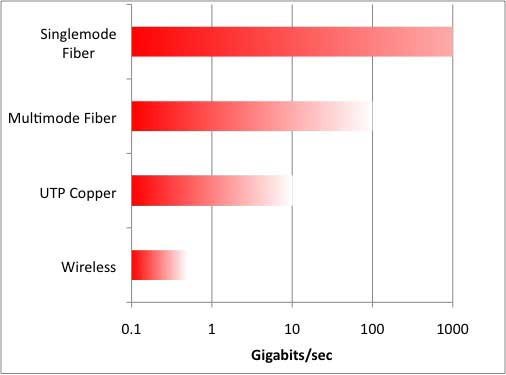
Working Speeds For Various LAN Media
At the same time, new fiber to the home (FTTH) architectures using a passive optical network (PON) or point-to-point (P2P) links became cost-effective for broadband connections. In the first 5 years of active FTTH installations, almost 100 million homes, apartments and businesses were directly connected on fiber. Such high volume means prices dropped enough to make the cost of a singlemode fiber link as cheap as copper, or even cheaper when singlemode fiber's higher bandwidth capacity allowed for multiple users to share one fiber link.
Once suppliers and users realized that a premises LAN was not much different than an apartment building (called a MDU - multi-dwelling unit - in FTTH jargon) the FTTH architecture began being used in large LANs. By "large" we mean they started with LANs covering large geographic areas like a campus or large building as well as "large" in numbers of users, typically hundreds or thousands of users.
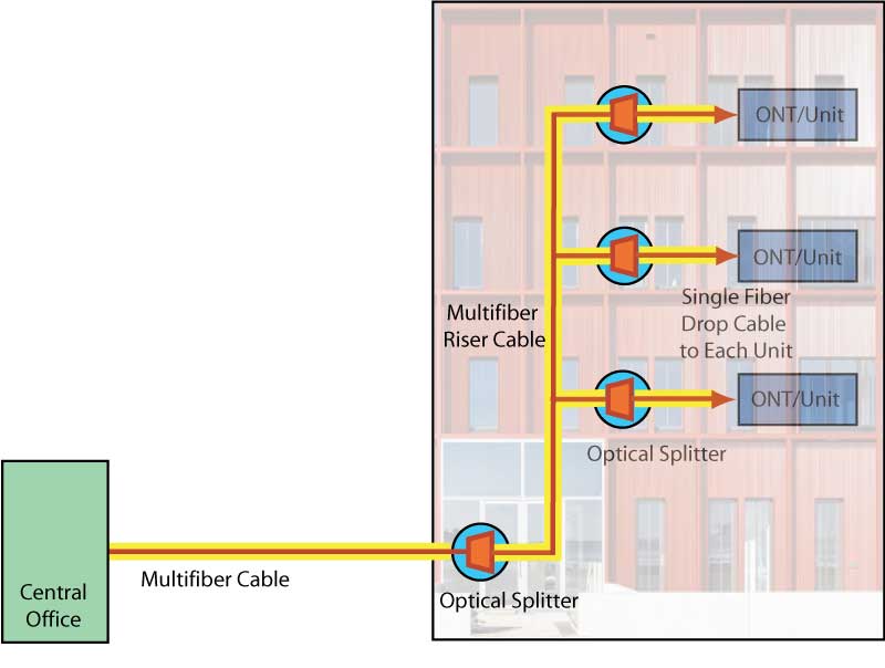
FTTH in a Multi-Dwelling Unit
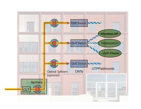
Passive Optical OLAN in Office Building
These applications became known as "passive optical LANs" (POLs) when using FTTH PON technology and "fiber to the office" (FTTO) when using P2P links. Collectively they are being called OLANs for "optical LANs). OLANs are based on international standards for FTTH but are being considered to be included in the structured cabling standards in the future.
Both FTTO and POL use multiport mini-switches at the user outlet. POLs are designed for triple play services (voice, data and video) but may only carry the services needed by the user. FTTO outlets are usually multiport Ethernet. Data ports are generally Gigabit Ethernet but upgrades to higher bit rates may be done. User terminals may have POE (power over Ethernet) available using the local powering for the ONT or switch.
OLANs are ideal solutions for many networks. They are essentially not distance limited, so they are ideal for large buildings (convention centers, airports, libraries, sports facilities, hospitals, etc.) or campuses. They scale easily to large networks, with networks of 16,000 users already installed. They use little space compared to traditional structured cabling networks. Not only are telecom rooms not needed, but the entrance facility electronics are small too. And the networks easily accommodate very high data usage; some can handle 10-20Gb/s connections to the outside world. POLs also have another advantage in security. Since they broadcast through a PON splitter to all users, each signal must be encrypted, adding a layer of security for the network.
Here are two examples of Optical LANs.
Fiber To The Office (FTTO)
Fiber to the office is a simple development of centralized fiber in structured cabling architecture, except it uses lower cost components designed for FTTH.
This is the network for Terminal 3 at the Dubai Airport as designed by Cliff Walker. It uses P2P links to 4 port switches. FTTO was chosen in part because of the sheer size of the terminal which made copper or MM fiber unfeasible. This architecture is similar to centralized fiber optics in structured cabling standards except it uses FTTH hardware, including singlemode fiber. Here is Cliff Walker's paper on this FTTO application.

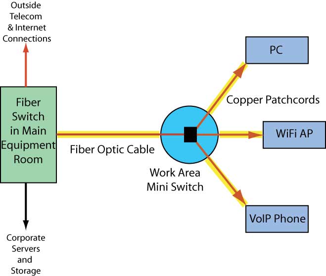
Here is the diagram of the FTTO network.
More On Centralized Cabling - Fiber to the Desk and Fiber To The Office
Passive Optical LANs (POLs)
The new San Diego central library encompasses 9 floors of library and technical high school. There will be over 1000 drops with 4 port ONTs that support 4000 users.
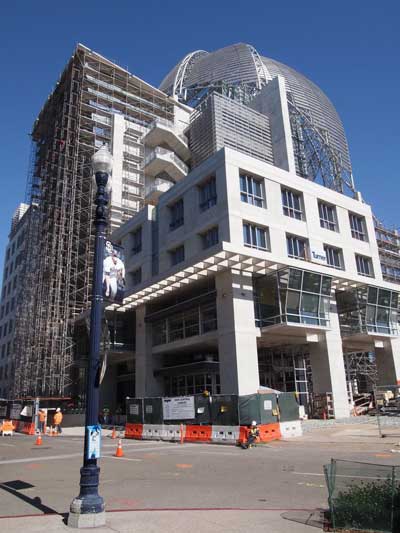
See more pictures from the SD Library.
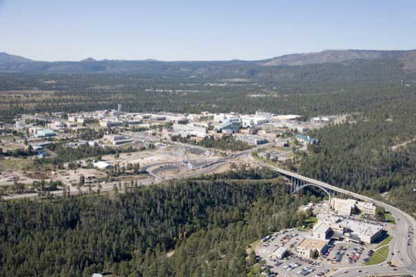
Sandia National Labs in Los Alamos, NM is much bigger. The passive optical LAN there covers 13,000+ users (50k ports) in 265 buildings. It cost $15M, with savings of $20M expected over a traditional structured cabling system. Using a POL reduced energy costs by 65% and created $80,000 in recycled copper cabling.
How Does An OLAN Differ From Traditional LANs?
Traditional LANs on structured cabling have limited distance links and are broken into backbone and horizontal sections. If implemented in copper or a combination of fiber and copper, they will have intermediate electronics in a telecom room. OLANs centralize all the network electronics, eliminating the telecom closet, and only use intermediate patching points where one connects larger fiber count cables to drop cables. OLANs implemented in singlemode fiber are not distance limited for the typical LANs. In fact one could build a metropolitan LAN using OLAN equipment considering the distance capability of FTTH sysems.
Advantages/Disadvantages of OLANs
Advantages
- Both FTTO and POLs use SM fiber with no bandwidth limitations from the cable plant
- They take advantage of the technology and economics of FTTH with millions of installations
- Each work area switch needs only one singlemode fiber (POL) or two fibers (FTTO)
- The smaller number of cables and smaller cables makes for simpler, cheaper installation
- Both avoid masses of UTP copper cabling and required hardware (cable trays, patch panels, telecom rooms)
- POL switches are designed to connect directly with incoming telecom/Internet services as well as Ethernet devices
- Mini-switches and ONTs connect to all user devices (PCs, APs) over standard UTP "Cat 5" patchcords – no media converters required
- Voice, data and video are easily accommodated as is anything that runs over Ethernet
- They are about as “Future Proof” as you can get
- Cost is lower than traditional LAN architecture using structured cabling, both initial expense and operating costs, especially since POLs use ~1/5 as much power as traditional LANs.
Disadvantages
- Generally best for larger numbers of users (100-200+) although new equipment may make smaller LANs cost effective
- Requires installing singlemode fiber (but using prefab cables or prepolished/splice connectors simplify termination)
- Requires SM test equipment (OLTS is not a problem but requires a very high resolution SM OTDR which would not be needed for most installations)
Perhaps the best comparison is the installation of traditional UTP cabling versus the installation of singlemode fibers to a work area.
Here is a comparison of three types of fiber optic cables for a 4-port OLAN switch compared to the UTP Cat 5E cables to support horizontal runs for 4 users.
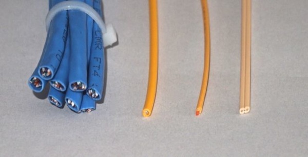
On the left, 8 Cat 5E cables. Next a 3mm simplex singlemode fiber cable, a 2mm cable and a special ruggedized FTTH drop cable with 2 fibers.
Optical fiber has so much less bulk, one does not need giant cable trays like in the hotel to the left. Even the conduit used in the San Diego Central Library for UTP cables dwarfs the simplex fiber optic cable needed to each work area.
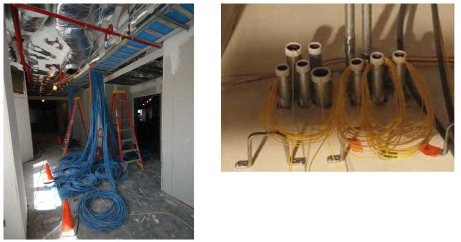
Another place the OLAN saves space is the computer room. Instead of racks of switches and trays full of Cat 5 cables, an OLAN facility looks more like this (the San Diego Central Library)
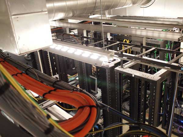
Looking down on the computer room, note the lack of cables. All you see are the orange ducts used for the fiber to remote splitters.
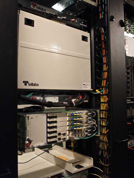
This is the networking hardware needed for 4000 user outlets at the library.
More On Passive Optical LANs
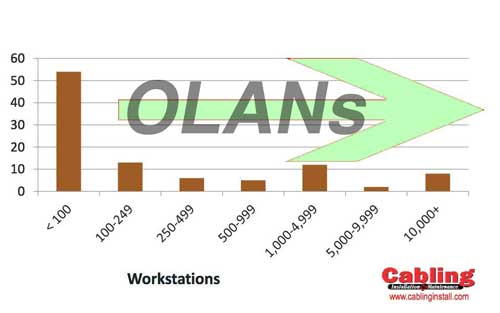
Where Do OLANs Make Sense?
OLANs work best in larger LANs where the savings will be greatest. Generally, any LAN with a few hundred users will benefit from an OLAN. Based on data from CI&M magazine, that means that ~45% of all LANs which include ~98% of all users are likely to benefit from OLANs. New equipment may make LANs of 100 users or less feasible with OLANs.
Typical users would be:
- Corporations
- Hotels and convention centers, casinos
- Hospitals
- Schools, campuses
- Public buildings, airports, convention centers
- Municipal networks
- Government and military facilities (some have standardized on OLANs already)
Summary
OLANs can be more cost effective, secure and provide better insurance against obsolescence than using traditional structured cabling.
More On OLANs
Introduction
Centralized Cabling - Fiber to the Desk and Fiber To The Office
Passive Optical LANs
Designing And Installing Optical LANs (OLANs)
Testing OLANs
Training And Certification
FOA has an Optical LAN (OLAN) specialist certification (CFOS/L) with training available from FOA approved schools. Read more.
Here are more sources of information on Optical LANs.
The FOA YouTube Lecture 30, OLANs, Optical LANs

There is a new trade association focusing on passive optical LANs: APOLAN
Tellabs
Zhone
Cliff Walker's FTTO paper
3M on POLs
TE Connectivity on Optical LAN Solutions
Corning Cable Systems on Optical LAN Solutions
Table of Contents: The FOA Reference Guide To Fiber Optics